Book Categories:

The Complete Engineering Guide to Heating Cables: Technology, Design, Installation, and Maintenance
Estimated reading time: 14 minutes
Quick-Reference Engineering Summary: An electric heating cable (also known as a heat trace cable or trace heating cable) converts electrical power into thermal energy via Joule heating. Installed along pipelines, storage vessels, valves, roofs, or beneath floor screeds, it counteracts radial thermal losses to the surrounding environment. Primary applications include industrial process temperature maintenance, freeze protection for mechanical piping, roof and gutter de-icing, and radiant electric underfloor heating.
Table of contents
- 1. Fundamentals of Electric Heat Tracing (EHT)
- 2. Heating Cable Classifications and Working Principles
- 3. Common Heating Cable Applications
- 4. Engineering Sizing and Circuit Design Methodology
- 5. Installation Standards and Field Practices (IEEE 515)
- 6. Quality Assurance: Three-Stage Insulation Resistance (Megger) Testing
- 7. Thermal Insulation and Outer Cladding Standards
- 8. Troubleshooting and Fault Resolution Guide
- 9. Preventive Maintenance Schedule
- 10. Frequently Asked Questions
- 11. Topic Cluster Strategy & Internal Links
- Need Engineering Support or Custom Manufacturing?
1. Fundamentals of Electric Heat Tracing (EHT)
1.1 Thermodynamics of Thermal Replacement
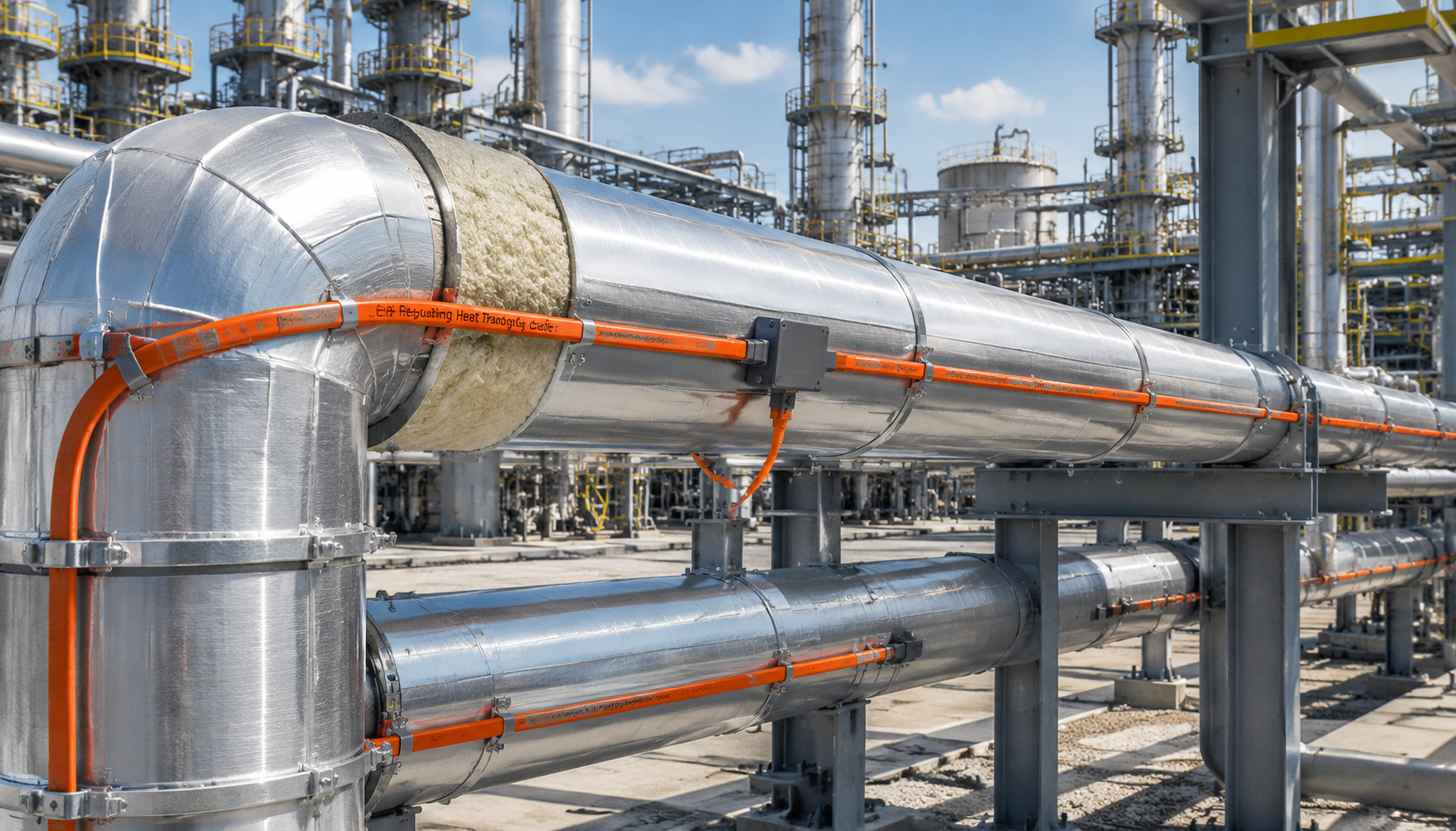
In municipal and industrial fluid transport, the fundamental objective of heat tracing is not bulk fluid preheating, but steady-state thermal equilibrium. When fluid flow stops in an unheated, insulated pipeline during sub-zero conditions, thermal energy conducts through the pipe wall, passes through the insulation core, and radiates into the surrounding air via external cladding.
To prevent fluid cooling or freezing, the heat trace system must continuously supply a thermal output (Q_cable) that balances or slightly exceeds Q_loss. You can model your line parameters with our online Pipe Heat Loss Calculator.
                 Radial Thermal Loss (Q_loss)
                           ↑ ↑ ↑ ↑ ↑
   +-----------------------------------------------------+
   |           Outer Weather Cladding (Aluminum/SS)      |
   |  +-----------------------------------------------+  |
   |  |        Thermal Insulation (Fiberglass/PIR)    |  |
   |  |  +-----------------------------------------+  |  |
   |  |  |           Process Pipe Wall             |  |  |
   |  |  |     [Fluid Stagnant at Maintain Tm]     |  |  |
   |  |  |                                         |  |  |
   |  |  +-----------------------------------------+  |  |
   |  |        ▲ [Electric Heating Cable (Q_cable)]   |  |
   |  +-----------------------------------------------+  |
   +-----------------------------------------------------+
                 Heat Input = Environmental Heat Loss
1.2 Electric Heat Tracing vs. Traditional Steam Tracing
Modern process plants continue to replace legacy steam tracers with electrical systems due to life-cycle maintenance costs and tighter temperature control:
| Operational Parameter | Electric Heat Tracing (EHT) | Steam Tracing |
|---|---|---|
| Temperature Control | Accurate to ±1°C via digital line-sensing thermostats | Crude; prone to line overheating or localized boiling |
| Thermal Efficiency | >95% heat transfer at pipe interface | 30% – 50% due to boiler, transport, and trap losses |
| Maintenance Demands | Low; annual megger checks and visual seal reviews | High; frequent steam trap leaks, water hammer, and corrosion |
| Water & Chemical Cost | Zero water usage; zero site emissions | Continuous boiler makeup water and chemical treatments |
| Installation Routing | Flexible routing around complex valves and flanges | Rigid piping runs requiring dedicated return loops and traps |
2. Heating Cable Classifications and Working Principles
Electric heating cables are classified by circuit construction and operational resistance behavior. The two primary categories used in commercial and industrial projects are Self-Regulating (PTC) and Constant Wattage cables.
2.1 Self-Regulating (PTC) Heating Cables
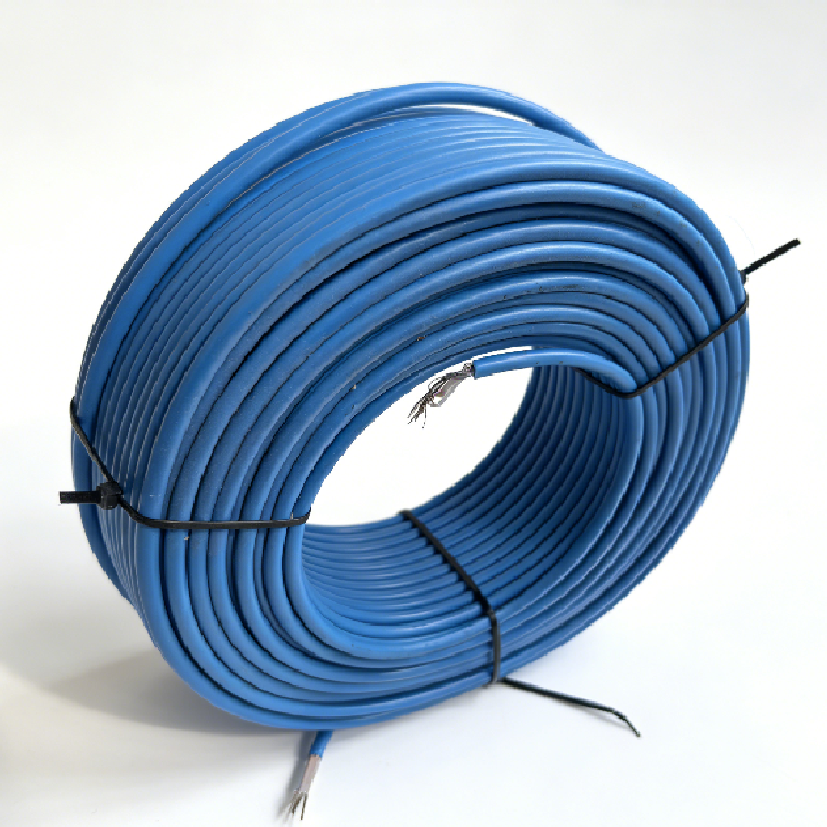
Self-regulating heating cables feature a conductive polymer core extruded between two parallel copper bus wires, surrounded by a primary dielectric jacket, tinned copper grounding braid, and an optional outer corrosion-proof jacket.
The Positive Temperature Coefficient (PTC) Effect:
- Cold Conditions (High Heat Output): At low pipe temperatures, the semi-conductive polymer matrix contracts microscopically. This brings carbon black particles into tight contact, establishing dense parallel conductive networks between bus wires and generating peak thermal output.
- Warm Conditions (Automatic Throttling): As pipe temperature approaches the setpoint, the polymer core expands microscopically. This separates the conductive carbon particles, disrupting circuit paths, raising electrical resistance, and naturally lowering wattage.
Cold Pipe Condition:                      Warm Pipe Condition:
Bus Wire (+)                              Bus Wire (+)
  │  ●──●──●──●  (Connected Carbon Paths)   │  ●    ●    ●   (Broken Conductive Paths)
  │  ●──●──●──●  → High Current, High Heat  │     ●    ●     → High Resistance, Low Heat
Bus Wire (-)                              Bus Wire (-)
Key Engineering Considerations:
- Safe Overlapping: Self-regulating cables adjust local wattage based on surface temperature, so overlapping turns at valves, flanges, or pumps will not cause hotspots or burnouts.
- Field Cut-to-Length: The parallel matrix construction allows installers to cut the cable to any length on-site without changing the rated watts-per-meter output.
- Cold-Start Inrush Surge: During cold startups (e.g., -10°C to -30°C), low core resistance draws a brief inrush current 2 to 3 times nominal operating current, requiring Type C or Type D circuit breakers.
2.2 Constant Wattage Heating Cables (Parallel Circuit)
Constant wattage heating cables consist of two parallel insulated copper bus wires surrounded by a spiraled alloy resistance wire (typically Nichrome). At designated intervals (heating zones), the inner insulation is notched, allowing the resistance wire to contact the bus wires alternately.
- Stable Power Profile: Output remains constant regardless of ambient or surface temperatures. A 20 W/m cable produces exactly 20 W/m from energization to shutoff.
- No Startup Inrush Current: Pure metallic resistance elements maintain stable resistance, drawing steady operating current without startup surges.
- Overlap Restriction: These cables must never cross or touch during installation. Overlapping traps heat between runs, exceeding the outer jacket’s continuous exposure limit and leading to jacket degradation, short circuits, or fire hazards.
- Cut-to-Length Rules: Cables can be cut in the field, but cuts must be made between zone nodes to prevent unpowered cold leads along the trimmed section.
2.3 Constant Wattage Heating Cables (Series Circuit)
Series resistance cables use continuous alloy conductor cores running the entire circuit length. The conductor functions simultaneously as the power-carrying bus and the thermal heating element.
- Long Run Capability: While parallel bus cables are limited by conductor current capacity to 100 m – 200 m runs, series cables support long pipelines with single-circuit lengths up to 1,500 m – 2,500 m from one power feed point.
- Factory Custom Built: Because total resistance depends on total length (R = r × L), series cables cannot be shortened or extended in the field. Every run must be engineered and terminated at the factory for specific voltages and lengths.
2.4 Mineral Insulated (MI) Heating Cables
Mineral Insulated (MI) cables are built for extreme industrial process temperatures that exceed the limits of organic polymer materials:
- Construction: Single or dual alloy resistance conductors embedded in compacted magnesium oxide (MgO) dielectric powder, enclosed within a seamless extruded metal sheath (Copper, Alloy 825, or Stainless Steel).
- High Temperature Limits: Withstands continuous exposure up to 600°C (1,112°F) and delivers watt densities exceeding 100 W/m. Used in refinery catalytic units, asphalt storage, and superheated steam lines.
2.5 Cable Selection Matrix
| Technical Parameter | Self-Regulating (PTC) | Constant Wattage (Parallel) | Constant Wattage (Series) | Mineral Insulated (MI) |
|---|---|---|---|---|
| Heating Core | Carbon-doped polymer | Spiraled Nichrome element | Continuous alloy core | Solid alloy core in MgO |
| Power Output Adjustment | Dynamic self-throttling | Fixed continuous output | Fixed continuous output | Fixed continuous output |
| Max Maintenance Temp | 65°C to 120°C | Up to 150°C | Up to 230°C | Up to 500°C |
| Max Exposure Temp | 85°C to 215°C | Up to 205°C | Up to 260°C | Up to 650°C+ |
| Field Cut-to-Length | Yes (Any point) | Yes (At zone nodes) | Strictly No | Strictly No |
| Permissible Overlap | Safe (Self-limiting) | Strictly Prohibited | Strictly Prohibited | Strictly Prohibited |
| Max Circuit Length | 80 m – 180 m | 100 m – 200 m | Up to 2,000 m | Up to 1,000 m |
| Inrush Current Factor | 2.0x to 3.0x nominal | 1.0x (Zero inrush) | 1.0x (Zero inrush) | 1.0x (Zero inrush) |
| Temperature Control | Ambient / Line sensing | Mandatory line sensing | Mandatory line sensing | Multi-point RTD / SCR |
3. Common Heating Cable Applications
3.1 Industrial Process Temperature Maintenance
Maintaining proper viscosity is critical for pumping heavy oils, resins, chemicals, and food products through industrial systems:
- Viscosity Stabilization: Heavy crude oil and asphalt must remain between 50°C and 110°C to prevent excessive pump head loss and line clogging.
- Crystallization Prevention: Caustic soda (50% NaOH) solidifies at approximately 12°C (53.6°F), requiring active freeze protection in cold climates. Learn more in our Industrial Pipe Freeze Protection Systems guide.
3.2 Commercial Building Freeze Protection
- Fire Protection Wet Mains: Fire sprinkler pipes in unheated parking garages and loading bays must remain above freezing without relying on chemical glycol additives.
- Potable & HVAC Piping: Roof chiller lines, cooling tower return loops, and exposed condensate drains require continuous freeze protection to prevent freeze-thaw bursts during utility outages.
3.3 Roof, Gutter, and Downspout De-Icing
Ice dams form when attic heat melts snow on upper roof decks, which then refreezes at unheated eaves. Trapped water can back up beneath shingles, causing interior structural water damage. Self-regulating cables with UV-rated jackets routed through gutters and downspouts maintain open drainage paths. See our layout guidelines for Roof and Gutter De-icing.
3.4 Outdoor Snow Melting
Installed beneath exterior concrete slabs, asphalt, or stone pavers, embedded heating cables deliver 250 W/m² to 350 W/m² to melt snow on hospital access ramps, parking entrances, and loading docks. This reduces slip hazards and eliminates corrosive chemical de-icers. Review system details under Snow Melting Systems.
3.5 Radiant Electric Underfloor Heating
In residential and commercial buildings, electric floor heating systems deliver steady, low-temperature radiant heat from the floor up:
- Pre-Spaced Heating Mats: Self-adhesive Fiberglass Mesh and Aluminum Foil Mats simplify installation under tile, engineered wood, and laminate floors.
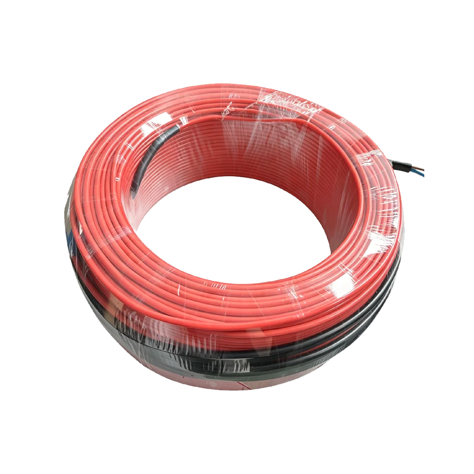
- Loose Heating Cables: Installed on fixing strips or membrane mats, loose cables allow flexible watt-density adjustments in irregular layouts. Discover options at Underfloor Heating Solutions.
4. Engineering Sizing and Circuit Design Methodology
Follow this step-by-step engineering process to design a reliable heat tracing circuit. You can verify your calculations with our online Heat Trace Cable Sizing Calculator.
- Calculate Heat Loss (Q_loss): Determine pipe diameter, insulation type, minimum ambient temperature, and wind exposure factors to establish the required heat replacement rate in W/m.
- Select Cable Wattage Rating: Match Q_loss to the manufacturer’s thermal output curve at the target maintain temperature (T_m). Note: Self-regulating output drops as the pipe warms; base your design on the output at T_m, not the nominal rating.
- Include Heat Sink Allowances: Add cable length for uninsulated components that conduct heat away faster than uniform pipe runs:
| Pipe Component / In-line Fitting | Additional Heat Trace Cable Required |
|---|---|
| Gate / Globe / Ball Valve | 1.5x to 2.5x the bare valve length (typically 0.5 m – 1.5 m) |
| Flange Pair | 2x the pipe diameter (typically 0.3 m – 0.6 m) |
| Pipe Support Shoe / Hanger | 0.2 m to 0.5 m along the support base |
| Process Pump Casing | 1.5x to 3.0x the pump casing body dimensions |
- Calculate Total Circuit Length: Multiply straight pipe length by any spiral tracing factor, add heat sink allowances, and include 0.5 m at each power connection, tee-splice, and end seal for termination connections.
- Verify Maximum Circuit Run Length: Compare total length against the cable’s maximum single-circuit run limit to prevent bus wire overloading or excessive voltage drop.
- Size Breakers for Cold-Start Inrush: Size branch circuit breakers with Type C or Type D trip curves rated at 125% of the calculated cold-start inrush current at the lowest expected ambient temperature.
- Select Temperature Controls: Pair the circuit with ambient-sensing or line-sensing Thermostats & Regulators equipped with RTD sensors and ground-fault protection.
5. Installation Standards and Field Practices (IEEE 515)
Proper installation according to IEEE 515 and IEC 60079-30 standards prevents premature field failures and ensures consistent heat transfer.
   CORRECT: 45° Offset (4 or 8 o'clock)           INCORRECT: Dead Bottom (6 o'clock)
             ┌─────────┐                                      ┌─────────┐
             │  Pipe   │                                      │  Pipe   │
          ●  │  Cross  │  ●                                   │  Cross  │
        (45°)│ Section │(45°)                                 │ Section │
             └─────────┘                                      └─────────┘
        Protected from leaks and impacts                           ●  <-- Risk of leak damage
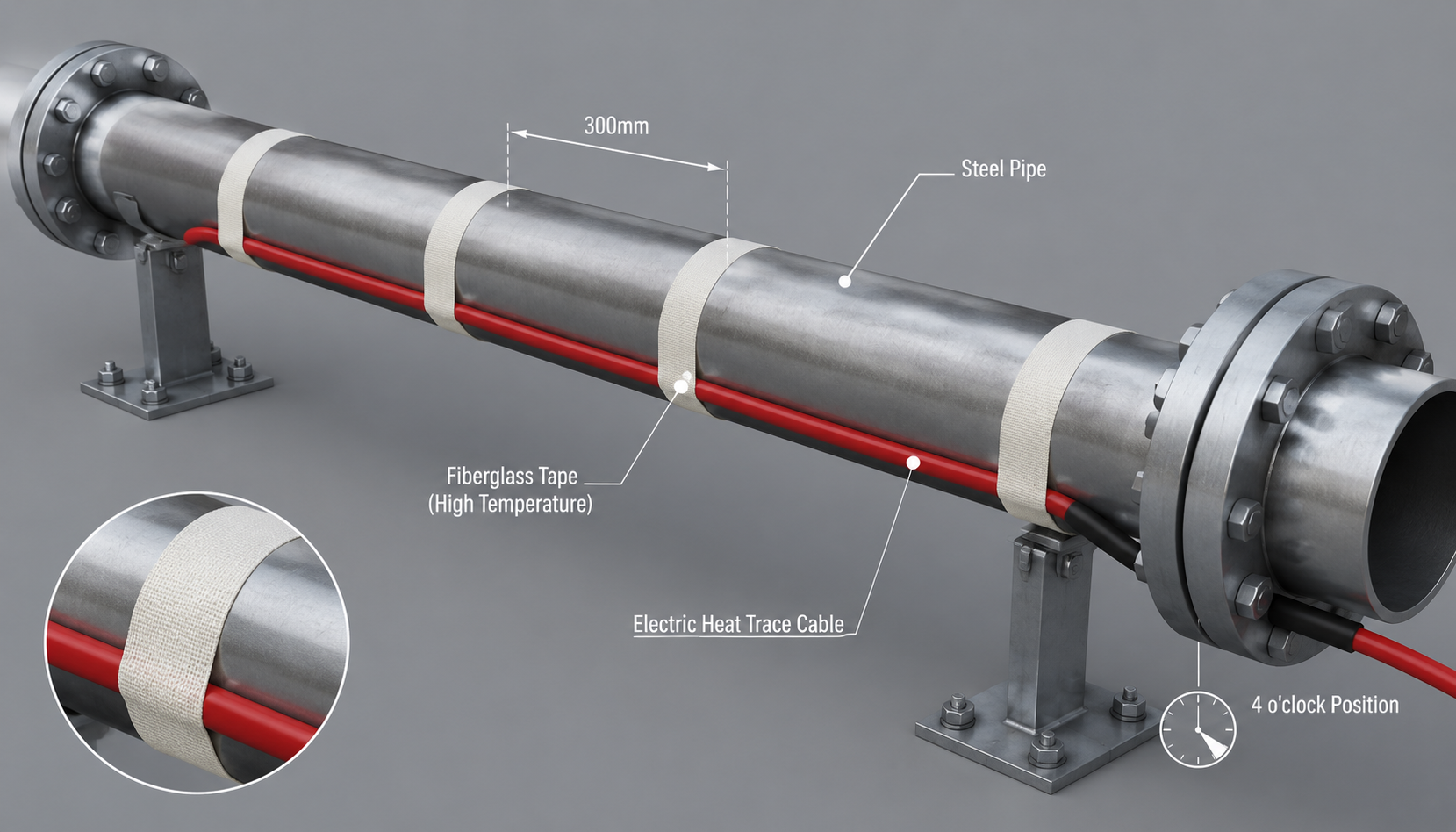
- 45° Lower Quadrant Placement: Install cables on horizontal pipe runs along the bottom quadrant at the 4 o’clock or 8 o’clock position. Placing cables at the bottom center (6 o’clock) leaves them vulnerable to flange leaks, chemical drips, and crushing during pipe maintenance. Placing them at top center (12 o’clock) results in convective heat loss away from the pipe.
- Bend Radius: Never exceed the minimum bend radius—typically 5 to 6 times the cable’s outer thickness. Do not make sharp 90° bends over fitting edges.
- Secure Fastening: Affix cables every 300 mm to 500 mm using temperature-rated fiberglass tape or aluminum tape. Never use metal baling wire, steel banding, or standard vinyl cable ties, which can cut into jackets or create hot spots.
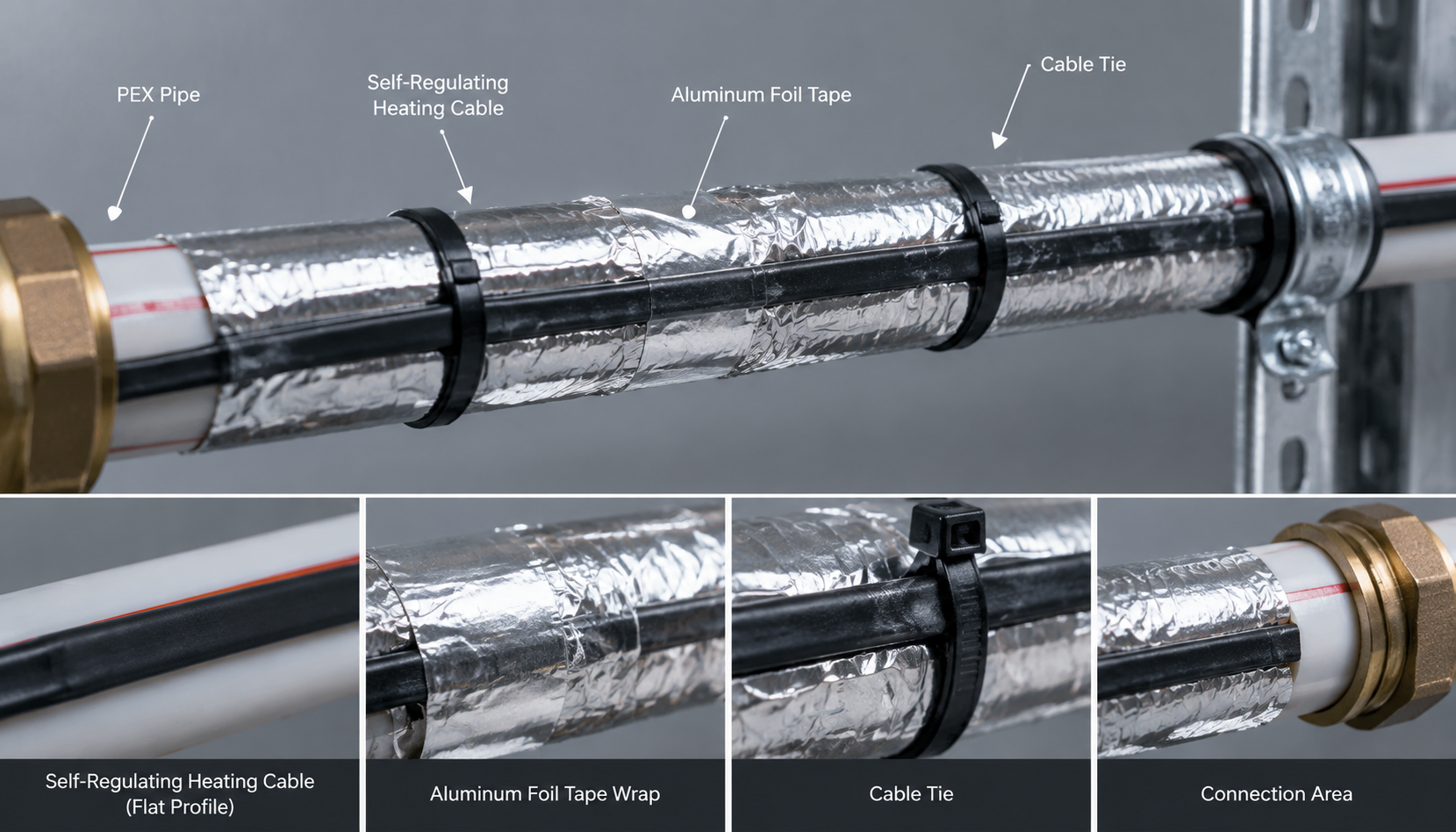
- Aluminum Tape for Plastic Pipes: When installing on PVC, CPVC, or HDPE lines, apply continuous aluminum foil tape over the cable. This spreads concentrated linear heat radially around the plastic pipe wall to prevent localized overheating.
- Wiring and Grounding: Use approved Installation Accessories & Junction Boxes. Terminate the metallic grounding braid to an earth ground with resistance ≤ 4.0 Ω. All circuits must include 30 mA Equipment Ground-Fault Protection (GFEP) breakers.
- Crucial Termination Rule: When sealing dead-end terminations, never twist the two internal bus conductors together. Doing so creates a direct line-to-line dead short upon energization.
6. Quality Assurance: Three-Stage Insulation Resistance (Megger) Testing
Insulation resistance (Megger) testing is critical for identifying jacket punctures or conductor damage before energizing the system. Tests must be performed between the bus wires tied together and the outer metallic grounding braid.
| Testing Stage | When Performed | Minimum Acceptance Limit | Primary Objective |
|---|---|---|---|
| Stage 1: Receiving | On shipping spool prior to installation | >100 MΩ @ 1000V DC | Verify no shipping or handling damage occurred |
| Stage 2: Post-Traced | Affixed to bare pipe, before insulation | >100 MΩ @ 1000V DC | Catch installation abrasions on valves and sharp fittings |
| Stage 3: Final Sign-off | After insulation and cladding are installed | >20 MΩ @ 1000V DC | Check for cladding screw punctures before energization |
7. Thermal Insulation and Outer Cladding Standards
Thermal insulation works as an integral part of the heat tracing system. Wet or poorly protected insulation significantly increases heat loss and leads to system freeze-ups.
- Keep Insulation Dry: Mineral wool, calcium silicate, and fiberglass insulation lose up to 80% of their thermal resistance when saturated with water. Stop installation and protect exposed piping with plastic sheeting if rain occurs during construction.
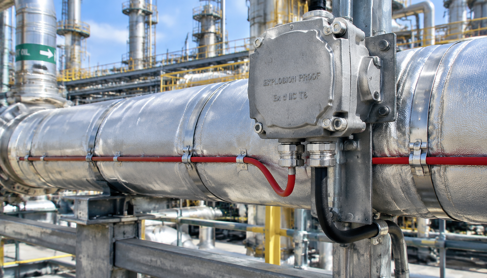
- Cladding Fastener Clearances: Do not use blind rivets or long self-tapping screws on sheet metal cladding over heat trace cables. Long screws can easily pierce the cable core, creating ground-fault shorts. Use short screws (≤ 9.5 mm / 3/8 in) or stainless steel cladding bands instead.
- Weatherproofing: Seal all cladding overlaps, valve cutouts, and support penetrations with neutral-cure silicone sealant to prevent moisture ingress.
- System Identification Labels: Affix high-visibility yellow “ELECTRIC HEAT TRACED” warning labels every 3 to 5 meters along the cladding, as well as near valves, splices, and junction boxes.
8. Troubleshooting and Fault Resolution Guide
When field faults occur, use this troubleshooting matrix to identify and correct root causes:
| Symptom | Probable Root Causes | Diagnostic Procedure | Corrective Action |
|---|---|---|---|
| Low Megger Reading (<20 MΩ) | • Cladding screw penetrated jacket • Water inside end seal or junction box • Wet, saturated insulation core | Isolate cable sections at inline tees. Test each run with a 1000V DC Megger. | Cut out damaged sections and install an inline splice kit. Dry and reseal all wet enclosures. |
| Breaker Trips on Startup | • High cold-start inrush current • Circuit run exceeds max length • Instantaneous breaker curve too fast | Measure cold-start peak current with an amp clamp during energization. | Upgrade to a Type C or Type D circuit breaker, split the run, or add a soft-start controller. |
| Immediate Dead Short Trip | • Bus wires twisted together at end seal • Bus conductor touching ground braid • Severed cable core | Check continuity across disconnected bus conductors with a digital multimeter. | Disassemble end seals; keep bus wires separated. Re-terminate power connections. |
| Low Pipe Temperature | • Loose cable contact on pipe wall • Wet insulation • Sensor mounted too close to cable | Check pipe temperature with an infrared pyrometer. Inspect insulation for moisture. | Re-tape cable with aluminum foil tape. Replace wet insulation. Move RTD sensor 90°–120° away from the cable. |
| Localized Cable Melting | • Constant wattage cable crossed over itself • Exposed to high-temperature steam lines • Controller relay stuck in closed position | Visual check for discolored or melted cladding. Test thermostat relay contacts. | Replace damaged cable. Ensure constant wattage runs never cross. Replace faulty thermostats. |
9. Preventive Maintenance Schedule
Electric heating cables have no moving mechanical parts, but regular seasonal inspections help identify issues before cold weather arrives:
- Autumn Pre-Winter Inspection (September – October):
- Perform a 1,000V DC insulation resistance check from the distribution panelboard. Log all values; investigate any circuit reading below 20 MΩ.
- Check junction box silicone seals, gaskets, and drain plugs for signs of moisture, cracking, or terminal corrosion.
- Cycle line-sensing thermostats manually to confirm relay contactor operation and verify current draw.
- Mid-Winter Operational Monitoring (December – January):
- Measure operating current on each circuit and compare against design calculations (I = P / V). Low current can indicate damaged parallel zones or broken splices.
- Perform thermal imaging (FLIR) scans along critical lines to identify cold spots, loose cable contact, or missing insulation.
- Spring Post-Maintenance Audit:
- After plant turnaround or mechanical pipe repairs, re-megger affected circuits to verify piping crews did not damage cables during valve servicing.
10. Frequently Asked Questions
What is the difference between a 5mA GFCI and a 30mA GFEP breaker in heat tracing?
Can heating cables be used on plastic pipes (PVC, CPVC, HDPE)?
What causes cold-start inrush current in self-regulating cables?
11. Topic Cluster Strategy & Internal Links
This pillar guide serves as the foundation for our detailed technical resources. Explore these cluster topics for in-depth engineering guides, installation handbooks, and design calculators:
- Product Technologies:
- System Applications:
- Calculators & Design Tools:
Need Engineering Support or Custom Manufacturing?
UF-Heat designs and manufactures international-standard certified electric heating cables, thermostats, and complete trace heating systems. Our engineering team assists with heat loss calculations, isometric drawing take-offs, and custom OEM manufacturing.
Get in touch with an engineer today via our UF-Heat Contact Page or size your project with our Heat Trace Engineering Tools.
| What to confirm | Why it matters |
|---|---|
| Pipe material | Compatibility requirements can differ for metal and plastic pipe systems. |
| Pipe outside diameter | Larger pipes usually have greater heat loss and may require a different design approach. |
| Heated length and layout | Valves, elbows, flanges, and branches can affect cable routing and accessory needs. |
| Lowest expected ambient temperature | The coldest design condition is central to freeze-protection planning. |
| Insulation type and thickness | Insulation reduces heat loss and affects cable output and operating efficiency. |
| Available voltage | The selected heating cable and controls must match the site power supply. |
| Control method | Thermostats and controllers help align operation with temperature conditions and energy goals. |
| Installation environment | Indoor, outdoor, wet, exposed, and regulated environments can have different product requirements. |