Book Categories:

Self-Regulating Heat Trace Sizing: How to Calculate Heat Loss & Cable Length
Bottom Line Up Front (BLUF): Precise heat trace calculation balances conductive and convective heat dissipation through insulated pipe walls using Fourier’s radial heat conduction equation. To size an industrial system accurately, calculate pipe heat loss at minimum design ambient temperature, add a mandatory 10% to 20% safety margin, and select a self-regulating cable matching or exceeding design watts per foot at the target maintenance temperature. Finally, incorporate thermal adder allowances for valves, flanges, and pipe supports to calculate total heat trace cable length.
What Are the Fundamentals of Pipe Heat Loss?
Industrial heat trace calculation determines the exact electrical thermal power needed to balance environmental heat dissipation. Thermal engineers must accurately balance this energy loss to maintain fluid viscosity and prevent costly freeze failures. Under-sizing heating cables creates catastrophic freeze-ups, while over-sizing significantly inflates capital expenditure and continuous power consumption. Modern engineering projects require systematic thermal loss formulas, reliable component multipliers, and proper cable selection metrics. This guide provides comprehensive mathematical derivations, real-world sizing rules, and an industrial worked engineering example.
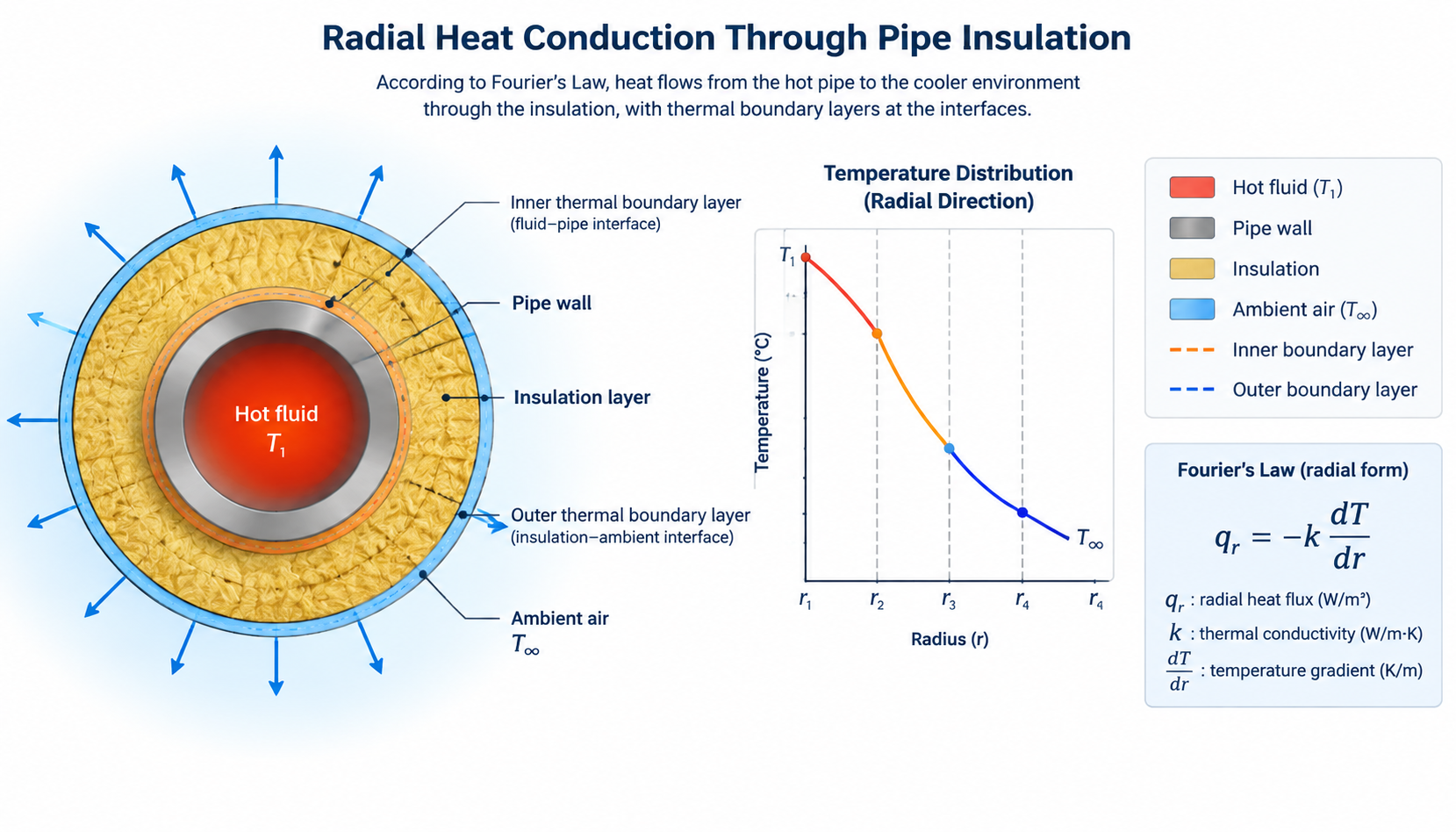
Pipe heat dissipation occurs through three simultaneous thermal transfer mechanisms: internal conduction, insulation conduction, and outer boundary convection. Thermal energy moves radially from the core process fluid through the metallic pipe wall toward ambient air. Fourier’s Law governs conductive heat transfer through the cylindrical insulation mantle enclosing the process pipework. Because metallic pipe walls provide minimal thermal resistance, the outer insulation layer governs total conductive thermal impedance. Convective and radiative heat transfer mechanisms dominate the exterior cladding boundary layer facing ambient atmospheric conditions.
Thermal boundary layers establish dynamic temperature gradients between the exterior insulation cladding and circulating atmospheric air. Natural convection occurs in dead-calm ambient conditions when buoyancy forces elevate warm air away from the jacket. Forced convection arises when ambient wind currents strip the warm boundary layer from the exterior cladding surface. Process piping standards published by ASHRAE define convective boundary layer behavior across complex industrial piping configurations. Controlling exterior jacket temperatures remains critical for overall thermal efficiency and hazardous-area personnel protection protocols.
How Do You Use the Pipe Heat Loss Formula?
Calculating heat loss requires steady-state cylindrical heat conduction equations modified by safety and environmental correction factors. The basic conductive formula computes thermal heat loss per unit length across circular insulation boundaries. In industrial electric heat tracing sizing, engineers express calculated thermal dissipation in Watts per meter or Watts per foot. The fundamental steady-state radial heat loss equation for insulated piping systems is expressed as follows:
$$Q = \frac{2 \pi \cdot k \cdot (T_m – T_a)}{\ln(D_o / D_i)} \times S_f$$
Where the individual design variables represent:
- Q: Pipe heat loss per unit length (expressed in W/m or W/ft).
- k: Thermal conductivity of insulation material at design mean temperature (W/m·K or Btu·in/hr·ft²·°F).
- Tm: Target fluid maintenance temperature (°C or °F).
- Ta: Minimum design ambient temperature expected on-site (°C or °F).
- Do: Outer diameter of thermal insulation jacket (mm or inches).
- Di: Inner diameter of thermal insulation, equivalent to pipe outer diameter (mm or inches).
- Sf: Design safety margin factor, recommended between 1.10 and 1.20.
To convert calculated metric thermal dissipation into Imperial units, engineers apply standard mathematical physical conversion factors. Dividing Watts per meter by 3.2808 yields heat trace watts per foot required for North American specifications. Engineering standards such as IEC 60079-30-1 specify a mandatory safety margin factor ranging between 10% and 20%. This safety factor accommodates unavoidable insulation compression, minor atmospheric moisture infiltration, and normal cable output aging. Thermal design technicians must never omit this design safety factor during initial system calculation phases.
How Do Insulation Type, Thickness, and Wind Affect Heat Loss?
Thermal insulation material selection dictates the effective thermal conductivity factor, commonly known as the material k-factor. The k-factor of thermal insulation materials varies significantly as a function of the operational mean temperature. Lower thermal conductivity ratings signify superior insulation efficiency, which directly reduces required electric heat tracing cable wattage. Specifiers frequently utilize fiberglass, closed-cell elastomeric foam, calcium silicate, cellular glass, and rigid mineral wool insulation. Moisture ingress severely degrades insulation performance, increasing thermal conductivity and resulting in unexpected piping freeze-up risks.
| Insulation Material | Typical k-Factor (W/m·K at 24°C) | Max Operating Temp (°C) | Moisture Resistance | Typical Application |
|---|---|---|---|---|
| Expanded Fiberglass | 0.033 – 0.038 | 454°C | Low to Moderate | General industrial piping, freeze protection |
| Mineral Wool | 0.035 – 0.042 | 650°C | Moderate | High-temperature process maintenance lines |
| Calcium Silicate | 0.055 – 0.065 | 650°C | Very Low | Heavy industrial steam systems, structural resistance |
| Cellular Glass | 0.040 – 0.048 | 430°C | Impervious (Zero) | Chemical processing, cryogenic, outdoor burial |
| Polyurethane Foam | 0.023 – 0.028 | 110°C | High (Closed Cell) | Chilled water lines, pre-insulated pipe networks |
Increasing insulation thickness produces diminishing thermal returns due to logarithmic increases in exterior surface dissipation area. Doubling insulation wall thickness does not halve thermal energy losses because outer convection surface area simultaneously expands. For outdoor installations, high ambient wind speeds actively strip insulating boundary air films from exterior metal cladding. IEEE and ASHRAE design standards recommend incorporating an active wind chill correction factor of 1.10 to 1.25. Specifying weatherproof aluminum or stainless steel jacketing ensures protective weatherproofing against outdoor atmospheric wind and moisture ingress.
How Do You Select Cable Output Wattage for Temperature Maintenance?
Self-regulating heating cables utilize a dynamic semi-conductive polymer matrix extruded between parallel copper bus wires. As process temperatures decrease, microscopic electrical pathways expand across the conductive polymer core, automatically increasing heat output. Conversely, rising pipe temperatures cause the polymer matrix to contract microscopically, reliably reducing local electrical wattage consumption. Heating cable manufacturers publish standardized thermal power curves indicating dynamic output wattages relative to prevailing pipe temperatures. Engineers must verify that the selected cable delivers sufficient thermal wattage at the target maintenance temperature.
Nominal cable output ratings reflect laboratory performance tested at standard baseline temperatures, typically 10°C (50°F). For example, a 10 W/ft cable provides 10 watts per foot only when the pipe temperature equals 10°C. If your pipe maintenance temperature rises to 50°C, the cable output naturally diminishes along its operational power curve. Cable compliance with recognized safety benchmarks, such as those evaluated by UL heating cable certification, ensures safe, dependable performance. Always cross-reference the manufacturer power curve against your calculated pipe heat loss before selecting heating cables.
| Pipe Maintenance Target | Calculated Heat Loss (W/m) | Recommended Cable Base Rating (at 10°C) | Installation Technique |
|---|---|---|---|
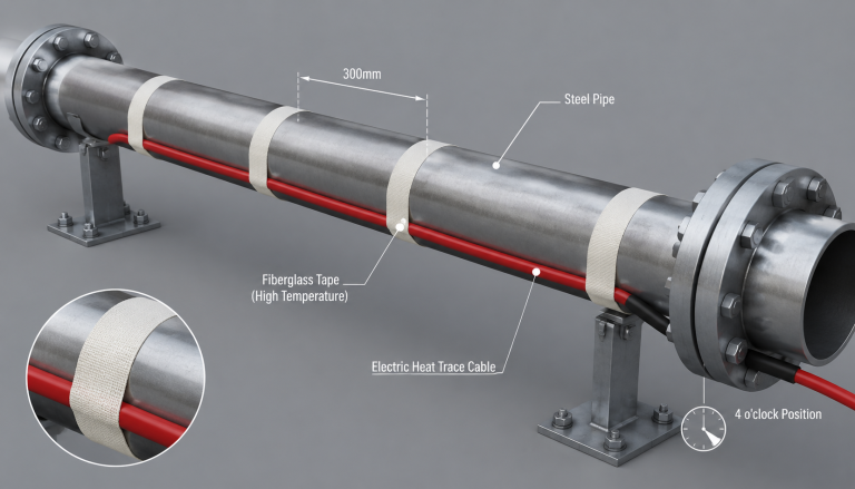
| 5°C (Freeze Protection) | 12 – 18 W/m | 16 W/m (5 W/ft) | Single straight run along 4 or 8 o’clock position |
| 5°C (Severe Sub-Zero) | 22 – 30 W/m | 33 W/m (10 W/ft) | Single straight run or spiraled application |
| 40°C (Viscosity Control) | 15 – 25 W/m | 33 W/m (10 W/ft) | Single straight run with electronic ambient control |
| 65°C (Fuel Oil Transport) | 35 – 50 W/m | 45 – 60 W/m (15 W/ft) | Dual parallel runs or high-temp power-limiting cable |
How Do You Account for Valve and Pipe Support Heat Loss Multipliers?
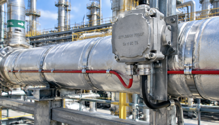
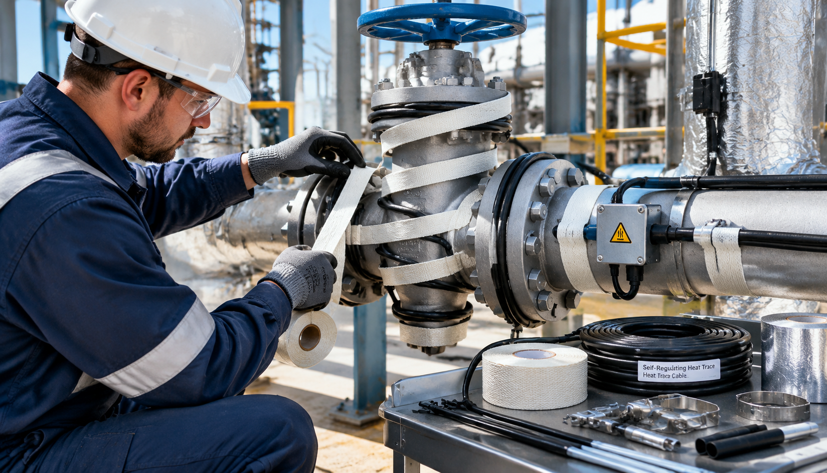
Valves, pipe flanges, and structural pipe supports act as massive thermal heat sinks along process pipelines. These uninsulated or partially insulated metallic components dissipate significantly more thermal energy than equivalent lengths of straight pipe. To calculate heat trace cable length accurately, designers add supplemental cable allowances to wrap around these components. Failure to allocate adequate heating cable length at valves causes localized cold spots and catastrophic blockages. Standard engineering practice assigns fixed linear cable footage allowances based on specific pipeline valve sizes and geometries.
| Pipeline Component | Nominal Pipe Size (NPS) | Additional Cable Allowance (Meters) | Additional Cable Allowance (Feet) |
|---|---|---|---|
| Gate / Globe Valve | 2-inch (DN 50) | 0.6 – 0.9 m | 2.0 – 3.0 ft |
| Gate / Globe Valve | 3-inch (DN 80) | 0.9 – 1.2 m | 3.0 – 4.0 ft |
| Ball / Butterfly Valve | 3-inch (DN 80) | 0.5 – 0.8 m | 1.5 – 2.5 ft |
| Flange Pair (Uninsulated) | 3-inch (DN 80) | 0.5 m | 1.5 ft |
| Pipe Support Shoe | All Sizes | 0.6 – 1.0 m | 2.0 – 3.3 ft |
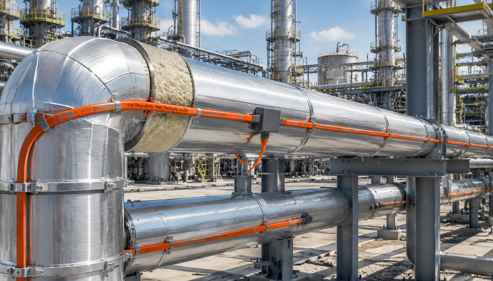
Total heat tracing cable circuit length incorporates straight pipe length, component adders, and necessary installation service loops. Technicians must provide extra cable length at electrical power connection points, end seals, and splice boxes. Standard engineering estimates add approximately one meter of supplementary cable per power connection box and tee-splice. Applying heating cables in a straight run along the lower pipe quadrant ensures optimal conductive heat transfer. Spiral tracing wraps become necessary only when calculated pipe heat loss exceeds maximum single-run cable thermal output capabilities.
Worked Example: Sizing a 3-Inch Outdoor Water Line at -25°C
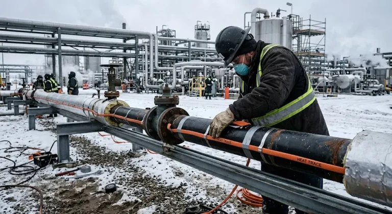
Let us execute a complete, step-by-step engineering heat trace calculation for a typical outdoor chemical process installation. This practical design scenario illustrates how engineers determine thermal heat dissipation, cable wattage, and total material requirements. Follow the structured calculation sequence below to verify system design requirements before ordering field installation materials.
1. Design Parameters & Environmental Conditions
- Pipe Specification: 3-inch NPS Schedule 40 Carbon Steel pipe (Outer Diameter $D_i = 88.9\text{ mm} = 0.0889\text{ m}$).
- Straight Pipe Run Length: 50 meters (164 feet).
- Process Fluid: Potable industrial service water.
- Target Maintenance Temperature ($T_m$): +5°C (41°F) for guaranteed anti-freeze protection.
- Minimum Design Ambient Temperature ($T_a$): -25°C (-13°F).
- Design Temperature Differential ($\Delta T$): $5°C – (-25°C) = 30°C$ ($54°F$).
- Insulation Material: Rigid preformed mineral wool ($k = 0.036\text{ W/m}\cdot\text{K}$).
- Insulation Thickness: 25 mm (1.0 inch), giving outer diameter $D_o = 88.9 + (2 \times 25) = 138.9\text{ mm} = 0.1389\text{ m}$.
- Inline Piping Components: 2 gate valves, 4 pairs of uninsulated flanges, 8 welded support shoes.
- Design Safety Factor ($S_f$): 1.15 (15% engineering safety margin).
- Atmospheric Wind Multiplier ($W_f$): 1.10 (accommodating outdoor 20 mph wind exposure).
2. Calculating Pipe Heat Loss ($Q$)
First, calculate the natural logarithm ratio between the outer insulation diameter and the inner pipe outer diameter. This geometric ratio governs radial conductive thermal resistance across circular insulation layers:
$$\ln(D_o / D_i) = \ln(138.9 / 88.9) = \ln(1.5624) = 0.4462$$
Next, substitute the parameters into the radial heat dissipation equation to establish base conductive pipe heat loss:
$$Q_{base} = \frac{2 \times \pi \times 0.036 \times 30}{0.4462} = \frac{6.7858}{0.4462} = 15.21\text{ W/m}$$
Now apply the required engineering design safety margin (1.15) and atmospheric outdoor wind correction factor (1.10):
$$Q_{design} = 15.21\text{ W/m} \times 1.15 \times 1.10 = 19.24\text{ W/m} \quad (5.86\text{ W/ft})$$
3. Cable Selection and Tracing Ratio
The system requires at least 19.24 W/m of heat output when the pipe sits at 5°C. Reviewing manufacturer performance curves, a 25 W/m (at 10°C) self-regulating cable produces 22 W/m at 5°C. Because 22 W/m exceeds our design target of 19.24 W/m, a single straight run is completely adequate. The installation tracing ratio equals 1.0, requiring no spiraling around the pipe.
4. Total Cable Length Calculation
Calculate the total heating cable procurement length by aggregating the straight run, component adders, and electrical termination allowances:
- Straight Pipe Length: $50.0\text{ m} \times 1.0 = 50.0\text{ m}$
- Gate Valves (2 units): $2 \times 1.0\text{ m} = 2.0\text{ m}$
- Flange Pairs (4 units): $4 \times 0.5\text{ m} = 2.0\text{ m}$
- Pipe Support Shoes (8 units): $8 \times 0.6\text{ m} = 4.8\text{ m}$
- Power Connection & End Seal Allowances: $1.0\text{ m} + 0.5\text{ m} = 1.5\text{ m}$
- Total Required Cable Length: $50.0 + 2.0 + 2.0 + 4.8 + 1.5 = 60.3\text{ m} \quad (198\text{ ft})$
What Should Specifiers Look for When Procuring Heat Trace Cables?
Industrial procurement teams must evaluate environmental hazards and chemical exposures when selecting commercial heat tracing cables. Standard polyolefin outer jackets provide exceptional mechanical strength and moisture protection in general water freeze-prevention installations. However, aggressive chemical environments containing organic hydrocarbons, acids, or solvents necessitate fluoropolymer outer protective jackets. Fluoropolymer jackets resist severe chemical degradation and ensure long-term mechanical reliability in demanding refining or petrochemical operations. Specifying the wrong outer jacket leads to rapid sheath embrittlement, moisture penetration, and catastrophic circuit trips.
Maximum exposure temperatures represent another vital procurement factor frequently overlooked by engineering procurement teams. Self-regulating heating cables feature two distinct temperature ratings: energized continuous operating limit and de-energized maximum withstand limit. High-temperature steam-out routines clean process pipelines rapidly but expose heating cables to extreme thermal surges. Exceeding cable exposure thresholds irreparably destroys the conductive core, permanently terminating electrical self-regulation characteristics. Always verify steam blowout temperatures against cable maximum withstand limits prior to final procurement sign-off.
Procurement professionals should also analyze manufacturer production quality, warranty guarantees, and regional testing compliance. Reputable manufacturers submit their heating products to rigorous third-party audits to guarantee flame retardance and electrical safety. Certified cables feature distinct serial tracking, clear wattage marking intervals, and robust mechanical construction. Furthermore, partnering directly with experienced thermal cable manufacturers shortens delivery lead times and delivers substantial cost savings. Technical support from experienced heating engineers streamlines circuit sizing and guarantees accurate system installation.
What Are the Critical Installation and Testing Requirements for Heat Tracing?
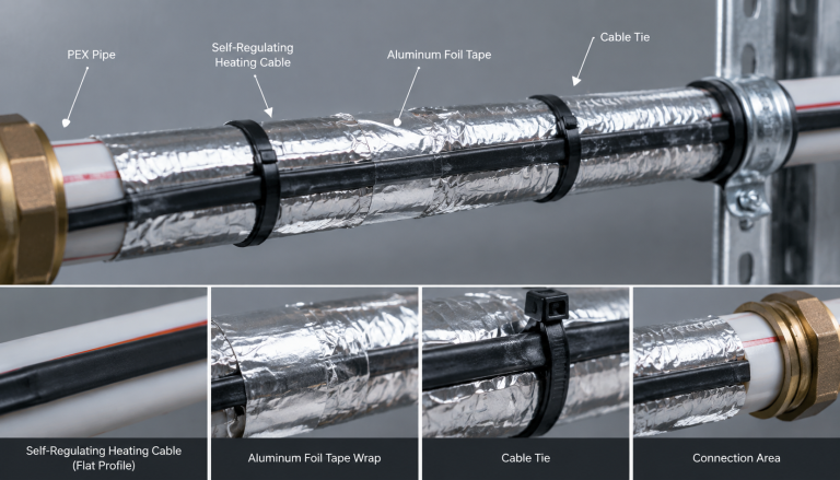
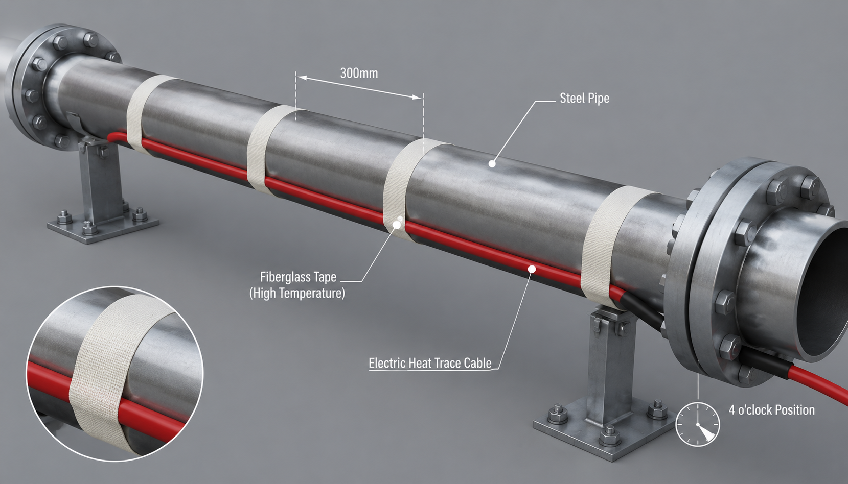
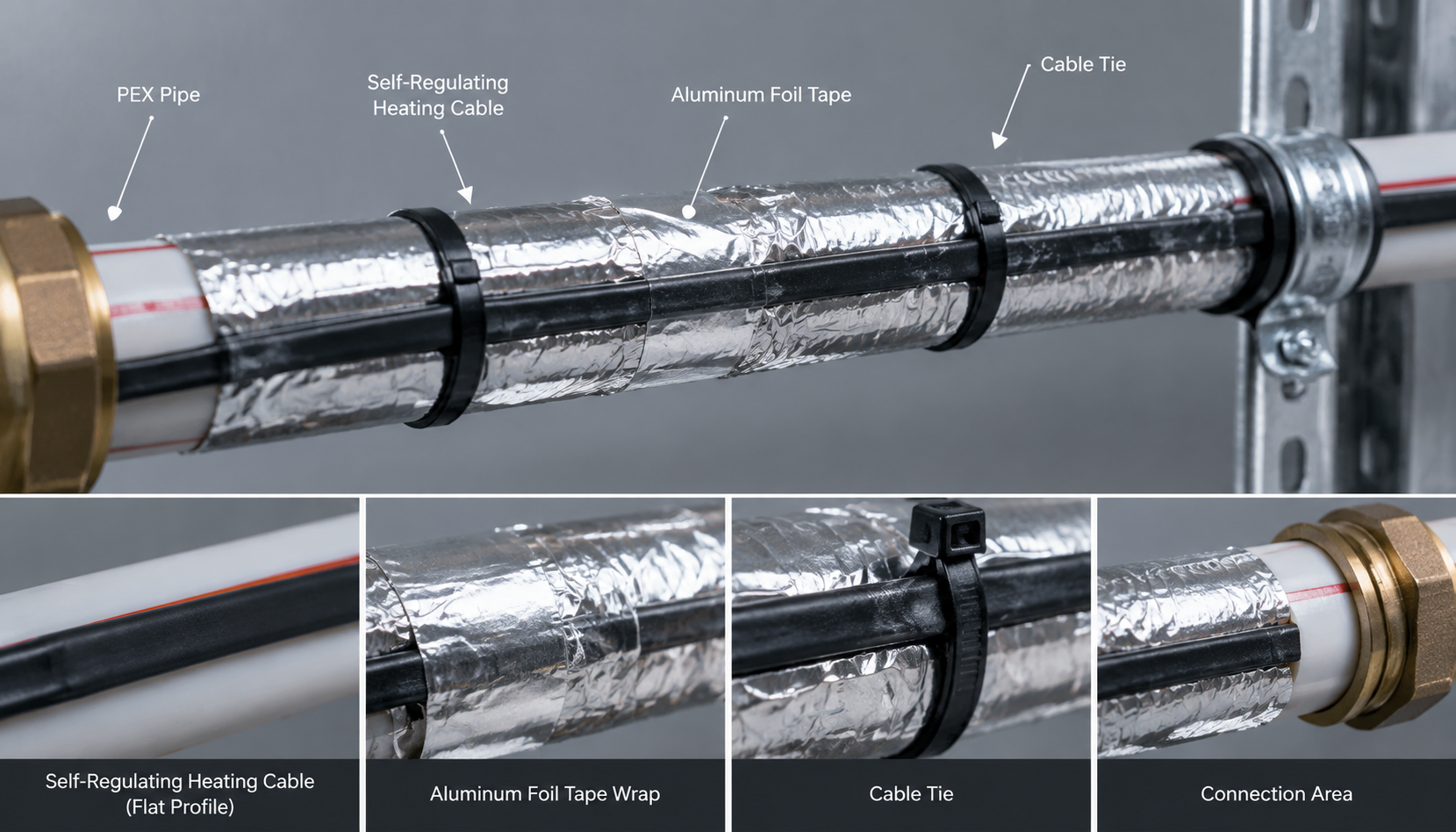
Proper installation practices safeguard electric heating systems against premature mechanical failure and hazardous electrical faults. Technicians must fasten heating cables to clean pipe surfaces using fiberglass tape at regular 300 mm intervals. Never use metal wire or plastic zip-ties, which sever protective insulation layers or compress the conductive core. Applying continuous aluminum foil tape over heating cables significantly improves thermal conduction into metallic and plastic pipes. Aluminum tape diffuses thermal energy around the pipe circumference, preventing localized hot spots and improving overall heating efficiency.
Electrical insulation resistance testing, commonly known as Megger testing, remains mandatory throughout the installation process. Technicians must perform Megger testing at 500 VDC, 1000 VDC, and 2500 VDC across three sequential milestones: upon receipt, after pipe mounting, and following insulation cladding completion. The minimum acceptable insulation resistance between the copper bus wires and outer metallic grounding braid is 20 megohms. Ground-fault circuit protection (GFEP) devices rated at 30 mA must protect all individual electric heat tracing circuits. These sensitive protective devices instantly de-energize electrical circuits when mechanical damage causes hazardous current leakages.
Frequently Asked Questions About Heat Trace Calculation
Can I calculate heat trace cable length without accounting for valves and pipe supports?
No, omitting valve and pipe support multipliers leads to severe heat loss and localized fluid freezing. Valves and uninsulated metal supports conduct heat away from pipelines rapidly, creating critical cold spots along the system. Always incorporate standard manufacturer adder lengths for all inline metallic components to maintain balanced, reliable pipeline temperatures.
Why does self-regulating heat trace require inrush current calculations?
Self-regulating heating cables exhibit significantly lower electrical resistance when cold, producing large electrical inrush surges upon startup. Initial startup currents can reach two to three times the rated nominal operating current for several minutes. Electrical engineers must size circuit breakers and power cables to absorb these momentary inrush surges safely without nuisance tripping.
How does ambient wind speed influence outdoor heat trace calculations?
Ambient wind accelerates convective heat loss by stripping the stagnant insulating boundary air layer from the pipe cladding. Unshielded outdoor piping systems exposed to 20 mph winds experience approximately 10% to 15% higher thermal dissipation. Design engineers incorporate wind multipliers or safety margins into the heat trace calculation to offset forced convection losses.
Can self-regulating heat trace cables overlap on the pipe?
Yes, self-regulating heating cables can safely cross and overlap without burning out or creating dangerous overheating zones. The conductive polymer core automatically throttles back local power output where temperatures rise at crossing contact points. In contrast, constant-wattage heating cables must never cross, as overlapping causes extreme localized overheating and cable destruction.
Partner with Youfu Thermal for Custom Thermal Engineering Solutions
Correct heat trace calculation protects your process pipelines against severe cold, costly downtime, and catastrophic freeze damage. Youfu Thermal manufactures premium industrial electric heat tracing cables, control thermostats, and engineering installation accessories. Our expert thermal engineering team delivers comprehensive pipe heat loss calculations, customized isometric circuit layouts, and tailored project quotations. Contact our engineering sales specialists today to review your project specifications and receive dependable, factory-direct thermal tracing solutions.