Book Categories:

Industrial Heat Tracing Systems: Explosion-Proof, High-Temp, and Hazardous Area Requirements
BLUF: An industrial heat tracing system operating in classified hazardous locations requires synchronized electrical design, robust mechanical shielding, and automated thermal throttling. Hazardous environments demand certified explosion proof heat cable—primarily high-temperature mineral insulated (MI) alloy cables or fluoropolymer self-regulating heaters—engineered strictly to Class I, Division 1/2 or Zone 1/2 standards. Compliance with IEEE 515, IEC 60079, and precise Temperature Class (T-Rating) calculations ensures continuous process temperature maintenance while eliminating ignition risks in volatile atmospheres.
How Do Class I Div 1 & Div 2 / Zone 1 & Zone 2 Hazardous Area Classifications Apply?
Hazardous area classifications determine the mandatory explosion-proof construction, grounding requirements, and certification levels for electrical heat tracing equipment. In North American facilities governed by the National Electrical Code (NEC), Class I locations contain flammable gases, vapors, or liquids. Division 1 locations feature ignitable concentrations of hazardous vapors continuously or intermittently during normal manufacturing operations. Conversely, Division 2 locations contain flammable substances only during accidental container ruptures or abnormal ventilation equipment failures.
International engineering projects follow the International Electrotechnical Commission (IEC) classification framework, which divides hazardous areas into Zone 0, Zone 1, and Zone 2. Zone 1 represents operating areas where explosive gas atmospheres regularly occur during typical everyday plant processing cycles. Meanwhile, Zone 2 encompasses industrial areas where hazardous vapor mixtures appear only infrequently and persist for brief operating durations. Consequently, engineering an industrial heat tracing system requires precise alignment with these defined geographic safety directives.
Deploying a hazardous area heat trace system inside Zone 1 or Division 1 boundaries requires third-party certified explosion-proof hardware. These rigorous safety certifications mandate continuous metallic grounding sheaths and specialized mechanical termination kits to prevent electrical arcing. Plant engineers should consult the official IEC 60079 standards for explosive atmospheres when calculating protective boundary limits. Installing fully compliant equipment prevents catastrophic vapor ignitions across offshore production platforms, pharmaceutical extraction plants, and chemical processing facilities.
What Are T-Ratings and Auto-Ignition Temperature Thresholds?
The Temperature Class (T-Rating) establishes the absolute maximum outer surface temperature that an electrical heating cable can generate under worst-case operational conditions. Under strict explosion prevention standards, the cable surface operating temperature must never exceed the auto-ignition temperature of surrounding airborne chemical vapors. Electrical engineers evaluate these critical thermal limits under simultaneous high line voltage, elevated ambient temperature, and pipe fluid stagnation. Selecting an incorrect T-rating introduces unacceptable combustion hazards into facilities handling volatile petroleum fuels and chemical reagents.
International safety standards establish six standardized T-ratings ranging from T1 (450°C) down to the exceptionally stringent T6 (85°C). Processing facilities handling combustible gases such as hydrogen, ethylene, or diethyl ether require rigorous adherence to lower T-ratings. As a practical engineering rule, the lower the maximum allowable surface temperature, the safer the installation remains in volatile environments. The following technical matrix illustrates standardized temperature classes alongside representative industrial compounds and their corresponding spontaneous combustion thresholds.
| Temperature Class (T-Rating) | Maximum Cable Surface Temperature (°C) | Auto-Ignition Safety Range (°C) | Representative Industrial Chemicals |
|---|---|---|---|
| T1 | 450°C | > 450°C | Methane, Hydrogen, Carbon Monoxide |
| T2 | 300°C | 300°C – 449°C | Acetylene, Propane, Ethanol, Butane |
| T3 | 200°C | 200°C – 299°C | Gasoline, Diesel Fuel, Kerosene, Hexane |
| T4 | 135°C | 135°C – 199°C | Acetaldehyde, Diethyl Ether (Lower Margin) |
| T5 | 100°C | 100°C – 134°C | Specialty Organic Solvents, Reagents |
| T6 | 85°C | 85°C – 99°C | Carbon Disulfide, Ethyl Nitrate |
Maintaining thermal compliance requires advanced system calculations supported by verified ASHRAE technical resources and industrial pipeline heat loss equations. Self-regulating heating cables inherently decrease their conductive power as pipe skin temperatures increase, providing autonomous surface temperature control. Conversely, constant wattage and mineral insulated cables require hardwired mechanical high-limit thermostats or digital safety limiters. Implementing verified physical temperature-limiting cutoffs ensures that the heat tracing system remains within certified hazardous area parameters permanently.
Fluoropolymer vs. Mineral Insulated (MI) Cable: Which Should You Choose?
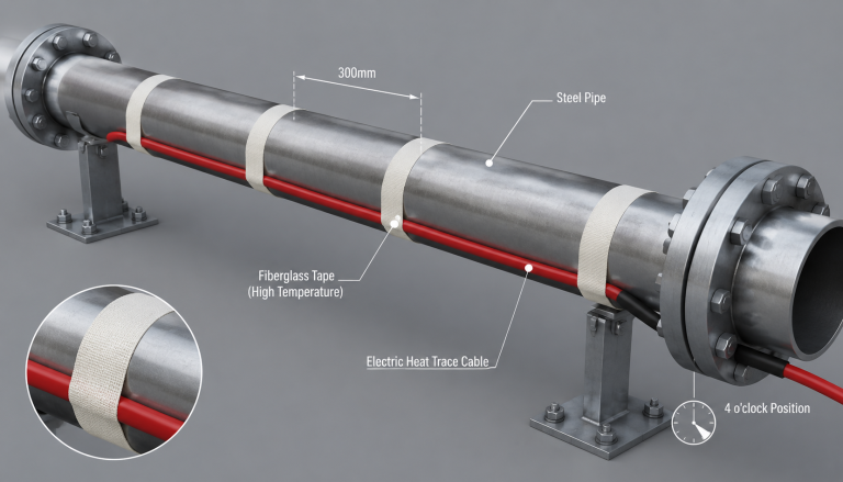
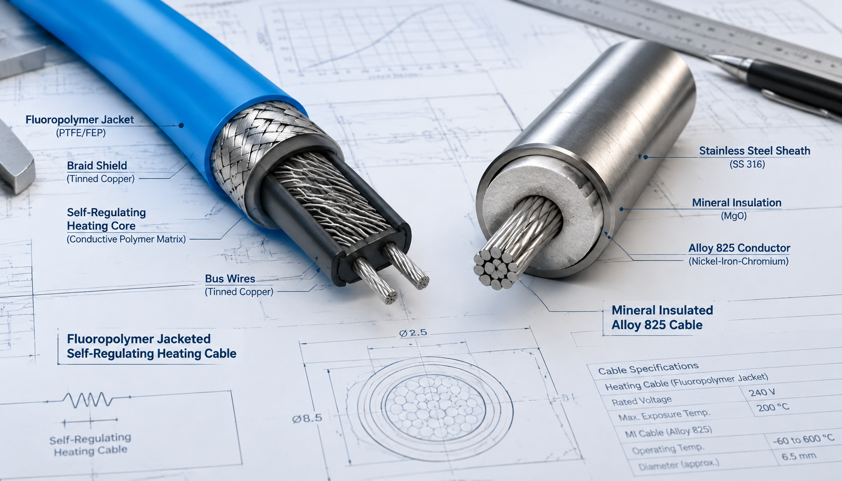
Selecting between fluoropolymer self-regulating cables and mineral insulated heating cables depends on maximum pipeline operating temperatures, chemical exposure, and mechanical stress. Self-regulating heating cables feature a semi-conductive carbon-polymer matrix core surrounded by dual nickel-plated copper bus conductors. An extruded fluoropolymer inner jacket, tinned copper grounding braid, and outer fluoropolymer overjacket provide superior resistance against corrosive chemical reagents. These flexible cables can be overlapped safely in the field without generating dangerous localized hotspots or physical burning.
However, polymer-based heating elements cannot withstand ultra-high continuous process maintenance temperatures or extreme thermal steam-out cleaning cycles. When piping conditions exceed 200°C, mineral insulated (MI) heating cables provide the only viable, reliable industrial engineering solution. An MI cable features solid resistance wire conductors embedded securely inside heavily compacted dielectric magnesium oxide (MgO) insulation. This internal assembly is encased within a continuous, pressure-tight metallic sheath fabricated from high-grade industrial alloys.
High-performance MI cables utilize specialized outer sheath alloys such as Incoloy 825, Stainless Steel 316, or Cupro-nickel. Incoloy 825 delivers exceptional resistance against chloride-induced stress corrosion cracking and pitting inside coastal refinery marine installations. Stainless steel 316 provides outstanding mechanical impact protection while resisting aggressive nitric acid solutions and heavy caustic wash chemicals. Furthermore, mineral insulated cables survive continuous operating exposures up to 600°C, making them essential for superheated steam operations.
| Performance Attribute | Fluoropolymer Self-Regulating Cable | Mineral Insulated (MI) Alloy Cable |
|---|---|---|
| Maximum Maintain Temperature | Up to 150°C (302°F) | Up to 600°C (1,112°F) |
| Maximum Exposure Temperature | Up to 250°C (482°F) | Up to 1,000°C (1,832°F) |
| Sheath Construction | Fluoropolymer Overjacket + Cu Braid | Alloy 825 / Stainless Steel 316 Sheath |
| Chemical Resistance | High (Acids, Hydrocarbons, Caustics) | Extreme (Solvents, Petrochemicals, Chlorides) |
| Mechanical Crush Resistance | Moderate (Impact-resistant braid) | Superior (Heavy-wall metal tubing) |
| Field Workability | Cut-to-length flexibility on site | Factory prefabricated set lengths required |
Why Are Power Connection and End Seal Kits Critical in Explosive Environments?
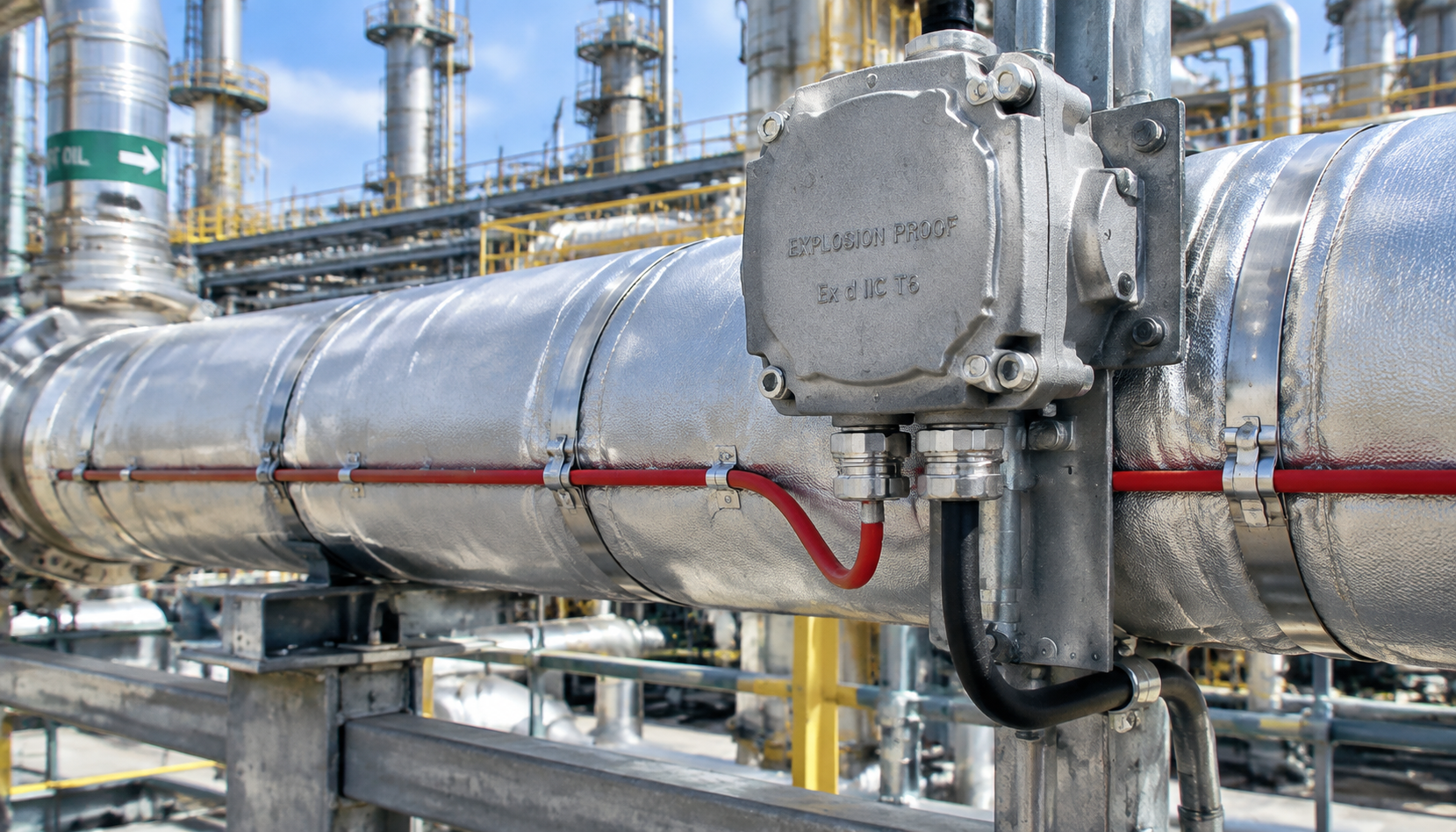
Field electrical termination points represent the most critical vulnerability across any hazardous area heat trace installation. Improperly sealed power connections, splice kits, and end seals permit volatile flammable gases and liquid moisture to infiltrate electrical junctions. To prevent destructive internal ignition, connection kits installed in classified environments must utilize flameproof Ex d or increased-safety Ex e certified enclosures. These ruggedized metallic enclosures are cast from heavy-wall copper-free aluminum or electro-polished 316 stainless steel to resist environmental deterioration.
Internal elastomeric grommets, high-grade silicone sealing boots, and precision conduit threads maintain an IP66 or NEMA 4X environmental ingress seal. Specialized cold lead transit kits isolate high-temperature heating conductors from sensitive lower-temperature wiring terminal blocks inside junction enclosures. In coastal and chemical environments, atmospheric moisture ingress causes devastating galvanic corrosion along metallic grounding braids, inducing sudden electrical faults. Consequently, specifying certified end seal assemblies prevents dangerous grounding failures and protects continuous plant operations.
Contractors must install ATEX certified heat trace connection components strictly following verified manufacturer specifications and standardized torque tolerances. Applying approved non-conductive silicone sealing compounds prevents external moisture penetration into the microscopic air gaps between electrical conductors. Additionally, certified conduit drain seals prevent combustible vapors from migrating through conduit runs into non-hazardous control equipment rooms. Conducting systematic physical inspections of all terminal box gaskets preserves the structural integrity of explosion-proof electrical systems.
How Do Modern Control and Monitoring Systems Integrate RTD Sensors with DCS Networks?
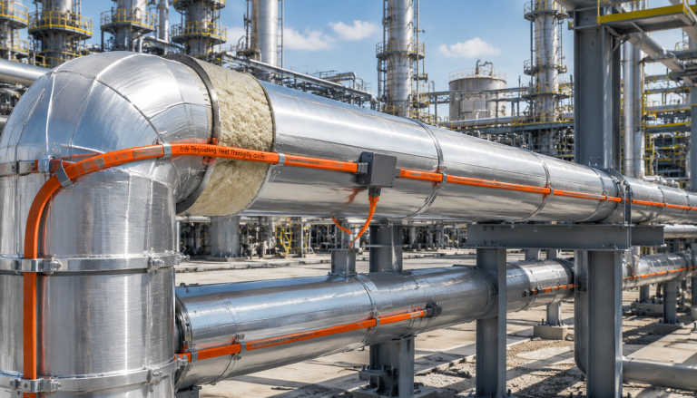
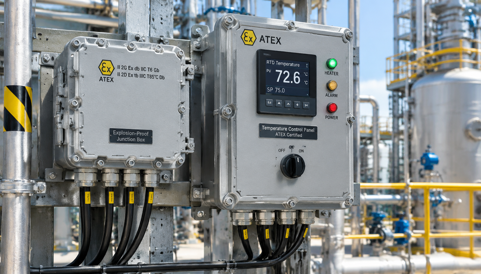
Automated temperature control systems balance energy efficiency with safety by managing heat trace output across complex piping loops. Industrial heat tracing systems deploy three-wire Platinum 100-ohm Resistance Temperature Detectors (RTDs) attached directly to pipe surfaces. These robust RTDs resist electromagnetic interference generated by neighboring variable frequency drives and heavy industrial plant switchgear. Dedicated microprocessor-based digital controllers continuously read these localized thermal sensors, dynamically adjusting solid-state power switching relays to preserve process fluid stability.
Modern processing plants link individual heat trace controllers directly into facility-wide Distributed Control Systems (DCS) using Modbus RTU or Profinet. Centralized DCS integration allows operations engineers to monitor line operating currents, pipe temperatures, and ground-fault levels in real time. Microprocessor controllers incorporate integrated Ground Fault Equipment Protection (GFEP) circuitry engineered to trip electrical breakers automatically at 30 milliamperes. Rapid breaker trip actuation eliminates destructive high-energy electrical arcing if external mechanical impact damages the heating cable sheath.
Furthermore, intelligent control platforms track gradual shifts in operating electrical resistance to identify emerging cable degradation before complete functional failure. Early warning alarm notifications alert maintenance personnel to localized insulation thinning, allowing proactive repairs during scheduled plant maintenance turnarounds. Integrating advanced digital controls protects valuable pipeline infrastructure while optimizing plant electrical efficiency across fluctuating seasonal ambient temperatures.
What Are the Key Commissioning and IEEE 515 Compliance Testing Protocols?
Commissioning an industrial heat tracing system requires comprehensive testing protocols to verify absolute electrical safety prior to system energization. The global engineering benchmark for these procedures is IEEE 515, which dictates testing rules for industrial electric resistance heat tracing. IEEE 515 mandates stringent quality assurance routines designed to uncover insulation damage inflicted during transit, installation, or thermal cladding construction. Technicians must conduct high-voltage direct-current insulation resistance testing utilizing a calibrated 2,500-volt DC Megohmmeter across all installed circuits.
Compliance guidelines require technicians to record insulation resistance values at three distinct project milestones: receiving, pipe installation, and final cladding. The electrical insulation resistance measured between internal heating bus wires and external metallic grounding sheaths must exceed 1,000 megohms. In addition, field personnel must reference product performance standards verified by UL heating cable testing and certification programs. Verifying grounding braid electrical continuity with precision micro-ohmmeters confirms that ground fault currents discharge safely during emergency breaker trips.
Final system commissioning includes an initial thermal energization test run to observe operating amperage, voltage stability, and pipe skin warming. Technicians record actual operational current draw against engineering heat-loss calculations to verify that controllers throttle heating circuits accurately. All measured insulation values, continuity readings, and operating data must be formally recorded in commissioning certification binders. Retaining this verification documentation preserves equipment warranties and validates continuous regulatory compliance with hazardous area operating permits.
What Factors Determine Industrial Heat Tracing System Selection and Procurement?
Specifying an industrial heat tracing system requires careful analysis of fluid chemistry, environmental hazards, thermal thresholds, and mechanical stressors. Procurement engineers must accurately determine heat loss metrics using pipe dimensions, thermal insulation efficiency, and minimum ambient site temperatures. Choosing undersized heating circuits risks costly fluid freezing and solidifying, while oversized cables cause unnecessary energy expenditure and accelerated component aging. Engineers should evaluate their facility requirements against the following technical criteria during equipment procurement planning.
- Hazardous Classification: Verify whether project zones require Class I, Div 1/2 or Zone 1/2 certifications (ATEX, IECEx, UL).
- Thermal Requirements: Identify maximum continuous process maintenance temperatures alongside peak exposure temperatures during pipeline steam-out cycles.
- Sheath Metallurgy: Specify Incoloy 825 or 316 Stainless Steel for extreme temperatures, mechanical impact, and corrosive chloride exposures.
- Chemical Compatibility: Choose heavy-duty fluoropolymer jackets for pipelines exposed to concentrated acids, industrial solvents, or petroleum hydrocarbons.
- Power Distribution: Calculate circuit breaker ratings, cold-start inrush currents, and transformer phase balancing across expansive pipe racks.
- Safety Controls: Mandate digital controllers equipped with integrated 30 mA ground fault interruption and direct DCS communications.
Procuring pre-engineered heating solutions from an experienced manufacturer guarantees full component interoperability and streamlines on-site contractor installation. Premium manufacturers provide matched power connection assemblies, mechanical mounting hardware, RTD sensors, and control panels tailored to challenging industrial environments. Standardizing on factory-certified heat tracing components reduces ongoing spare parts overhead and minimizes downtime during routine facility maintenance turnarounds. Investing in rugged industrial heating equipment ensures reliable performance and safe operation across demanding processing plants.
Frequently Asked Questions About Industrial Heat Tracing Systems
What is the fundamental operational difference between self-regulating and mineral insulated heating cables?
Self-regulating cables utilize a conductive carbon polymer core that automatically adjusts thermal power output based on localized pipe temperature variations. In contrast, mineral insulated cables utilize fixed-resistance metal alloy conductors insulated with magnesium oxide powder inside a heavy-duty metallic sheath. Mineral insulated cables deliver constant heat output and withstand extreme operational temperatures up to 600°C.
Why is Ground Fault Equipment Protection (GFEP) mandatory on all heat tracing circuits?
Ground Fault Equipment Protection set at 30 milliamperes is mandatory because conventional thermal-magnetic circuit breakers do not detect low-level arcing currents. In classified hazardous locations, low-amperage electrical arcing can ignite surrounding volatile vapors without drawing sufficient amperage to trip standard breakers. Sensitive ground fault protection immediately isolates the circuit upon detecting minute current leakage, eliminating severe ignition risks.
Can self-regulating heating cables be safely cut to length in the field?
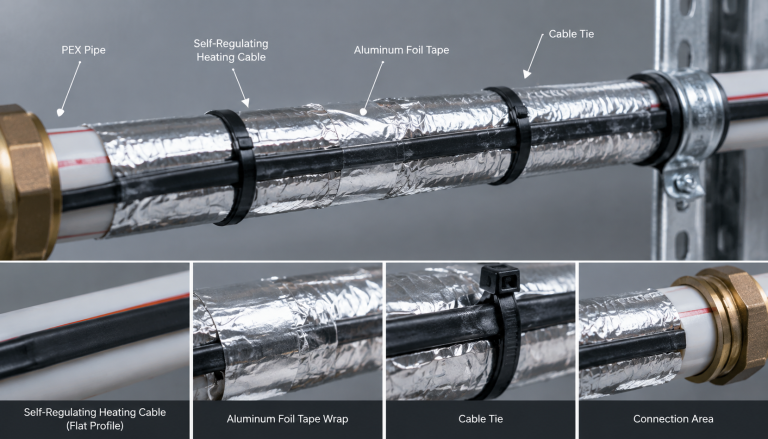
Yes, self-regulating heating cables can be cut to length directly in the field without altering their linear power output. Their parallel bus wire architecture delivers consistent wattage per meter regardless of total circuit length. However, contractors must terminate all field cuts using approved explosion-proof end seal kits certified for hazardous environments.
How frequently should hazardous area heat tracing installations undergo insulation resistance testing?
Industrial facilities should conduct comprehensive insulation resistance testing at least once every twelve months, ideally before the onset of winter. Facilities operating under severe vibration, thermal cycling, or corrosive environments should conduct testing biannually to identify early insulation breakdown. Regular preventive testing ensures full compliance with IEEE 515 standards and prevents unexpected freeze-ups.
What causes high cold-start inrush currents in self-regulating heat tracing cables?
At low startup temperatures, the microscopic electrical pathways within the semi-conductive carbon-polymer matrix expand, dramatically reducing electrical resistance. This low initial resistance draws significant startup electrical current until the core warms and stabilizes at its rated output. Electrical engineers must account for this initial inrush current when sizing circuit breakers and power distribution panels.
Engineered Heat Tracing Solutions for Demanding Industrial Projects
Youfu Thermal delivers engineered industrial electric heat tracing systems designed to perform safely in classified hazardous environments and extreme operating conditions. Our comprehensive product portfolio includes ATEX and IECEx certified self-regulating cables, constant wattage heating elements, and high-temperature Alloy 825 mineral insulated cables. Every heating system undergoes rigorous manufacturing quality controls to meet stringent international standards, including IEEE 515 and IEC 60079 compliance protocols. Whether your facility requires freeze protection for utility lines or high-temperature process maintenance, our technical engineering team provides custom thermal design, heat loss calculations, and dedicated project management. Contact our engineering team today to review your project specifications and secure an engineered heat tracing solution.