Book Categories:

How to Install Heat Trace Cable on Pipes: Step-by-Step Engineering Guide
Bottom Line Up Front: Installing heat trace cable on industrial piping requires systematic execution, rigorous electrical testing, and precise thermal component allowances. Field technicians must position the heating cable along the lower pipe quadrant while avoiding mechanical pinch points during construction. Engineers verify circuit integrity through multi-stage insulation resistance testing before and after applying pre-formed thermal insulation and protective cladding. Proper attachment using high-temperature tape ensures uniform heat transfer, which prevents localized freezing and catastrophic production downtime in cold environments.
What Tools, Materials, and Pre-Testing Procedures Are Mandatory?
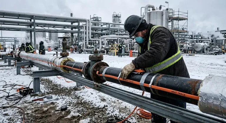
Professional pipe heat trace installation begins with a thorough inspection of the fluid piping surface and electrical materials. Maintenance teams must clean all pipe sections to remove loose rust, weld spatter, burrs, and residual oil grease. Furthermore, technicians should verify that the ambient temperature during installation aligns with the minimum handling limits of the heating cable. Handling heating cable below its rated installation temperature can fracture the protective outer jacket and compromise circuit insulation integrity.
Technicians must perform a calibrated insulation resistance test on every heating cable spool before beginning the physical layout. According to IEC 60079-30-1 and IEEE 515 international standards, workers should apply a direct current test voltage of at least 500 volts. Industrial facility specifications often require testing at 1000 volts or 2500 volts direct current for hazardous processing locations. A healthy heating cable must demonstrate an insulation resistance reading exceeding twenty megohms prior to active physical deployment. Youfu Thermal recommends recording every initial resistance measurement on the quality assurance documentation sheet for future baseline comparisons.
Technicians must prepare certified tools and approved hardware components before commencing the physical installation process:
- Calibrated direct current insulation resistance tester capable of producing test voltages from 500 to 2500 volts.
- Digital multimeter with calibrated leads for measuring total loop electrical resistance and circuit continuity.
- High-temperature fiberglass attachment tape designed specifically for industrial electric pipe tracing applications.
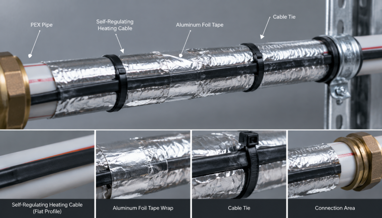
- Thermally conductive aluminum foil tape to distribute heat evenly across non-metallic and metallic pipe surfaces.
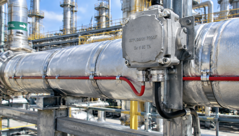
- Approved power connection kits, end terminations, and splice joints certified under UL testing and certification standards.
- Heavy-duty stainless steel banding and mechanical fasteners for securing heavy junction boxes and conduit supports.
How Should You Route Heat Trace Cable on Horizontal and Vertical Runs?
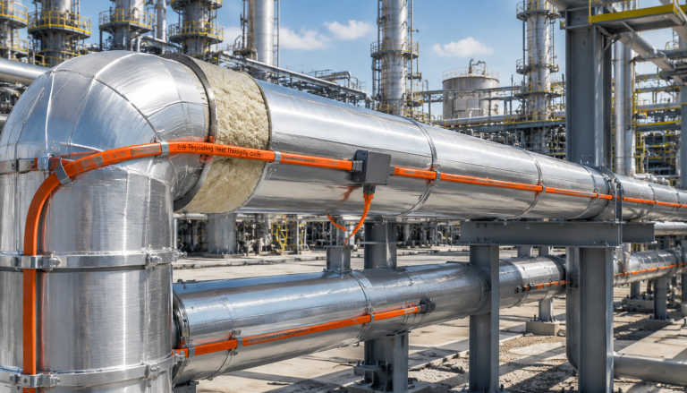
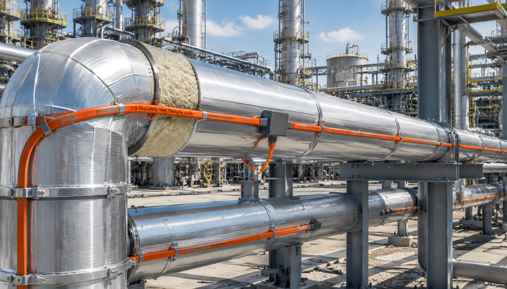
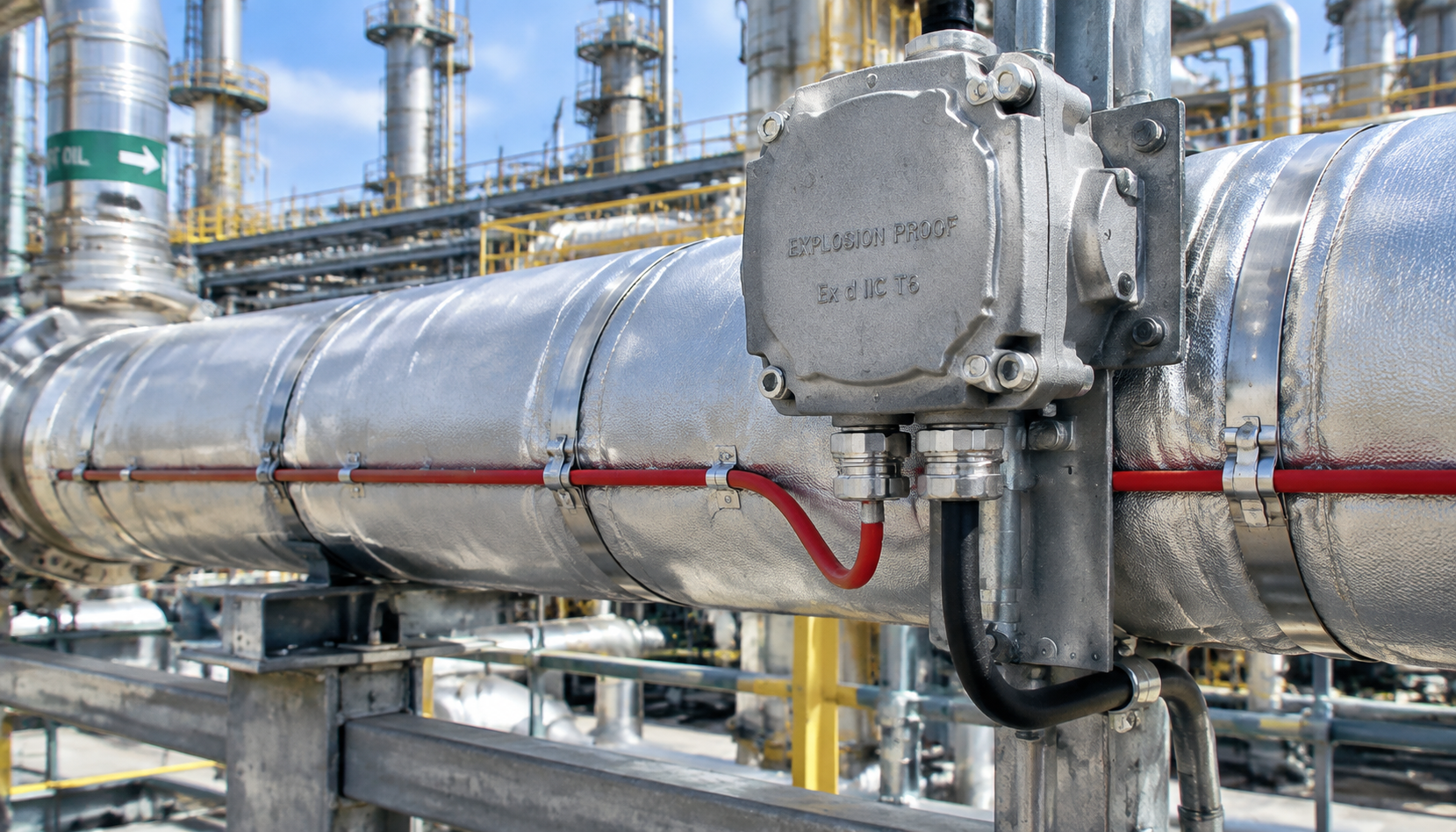
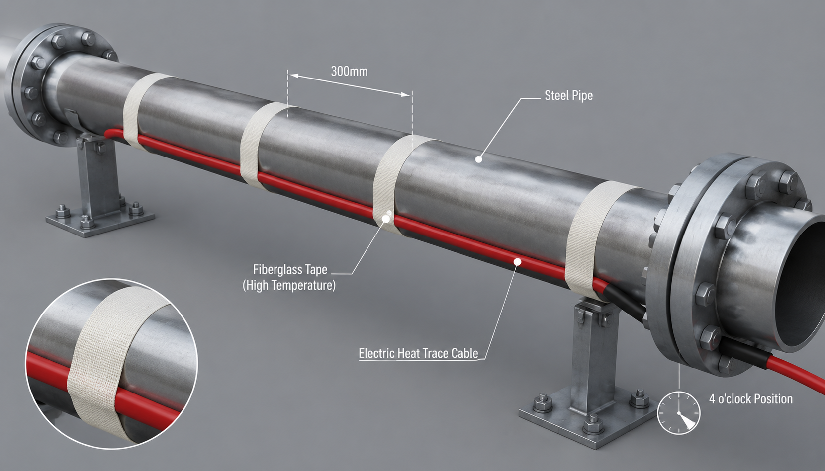
When technicians install heat trace cable on pipe systems, they must position the heating elements along the lower quadrants. Experienced engineers specify the four o’clock or eight o’clock positions to protect the heating elements from falling maintenance debris. Locating the heating cable directly at the six o’clock position exposes heating elements to mechanical crushing during pipe setting. Internal pipe sediment naturally gathers along the bottom channel, which inhibits uniform heat transfer into the circulating process fluids. Positioning the heating cable along the upper quadrant causes excessive heat loss because warm air rises away naturally.
Vertical pipe runs require consistent cable tension and rigid attachment intervals to prevent downward thermal cable slippage over time. Maintenance technicians should route the heating cable in a straight linear run along the sheltered side of vertical piping. If design calculations demand multiple cable passes, workers must space the parallel heating runs evenly around the pipe circumference. Workers must never wrap heating cable tightly around vertical pipes unless engineering documentation specifically designates a spiral installation design. Spiraling cable increases physical installation complexity and complicates subsequent thermal insulation placement during plant construction phases.
Mechanical bends along the piping route demand careful handling to prevent internal dielectric damage to the heating core matrix. Installers must maintain the minimum bend radius established by the manufacturer, which typically measures six times the cable diameter. Bending self-regulating cables across sharp structural corners creates microscopic dielectric fissures that lead to electrical arcing under high-load conditions. Consequently, technicians should route cables smoothly around pipe elbows, securing the trace along the exterior radius of the turn.
What Cable Allowances Are Required for Valves, Flanges, and Pumps?
Inline valves, heavy flanges, and structural pipe supports act as massive thermal heat sinks that dissipate heat energy rapidly. Installing heat tape on pipes without allocating additional cable length at these fittings leads to localized pipe freezing failures. Piping engineers calculate specific additional cable allowances to balance conductive heat losses across these large metallic surface areas. Technicians must trace these massive metallic fittings using continuous loops that facilitate routine mechanical maintenance without severing cables.
| Piping Component Type | Nominal Pipe Size (NPS) | Recommended Cable Allowance | Installation Pattern |
|---|---|---|---|
| Flange Pair (Standard ANSI 150#) | 1/2″ to 2″ (DN15 – DN50) | 0.3 m to 0.5 m (1.0 – 1.6 ft) | Straight pass with loop over flange rim |
| Flange Pair (Standard ANSI 300#) | 3″ to 8″ (DN80 – DN200) | 0.6 m to 0.9 m (2.0 – 3.0 ft) | Circumferential wrap inside bolt circle |
| Gate or Globe Valve | 1″ to 3″ (DN25 – DN80) | 0.6 m to 1.2 m (2.0 – 4.0 ft) | Serpentine loop across lower valve body |
| Gate or Globe Valve | 4″ to 10″ (DN100 – DN250) | 1.2 m to 2.5 m (4.0 – 8.2 ft) | Dual serpentine loop beneath bonnet neck |
| Structural Pipe Support Shoe | All Standard Pipe Diameters | 0.4 m to 0.8 m (1.3 – 2.6 ft) | Extended loop along support baseplate |
| Centrifugal Pump Housing | Small to Medium Industrial | 1.5 m to 3.0 m (5.0 – 10.0 ft) | Contoured trace along fluid volute case |
Technicians should apply a serpentine loop pattern over the main body casting of gate valves and globe valves. Maintenance teams can then remove valve bonnets and replace internal packing seals without cutting the active heat tracing circuit. Workers must maintain the minimum bending radius specified by the manufacturer when routing heating cables around complex valve bodies. Sharp metal edges on valve flanges and structural brackets must be smoothed or covered with protective aluminum tape layers. Securing the extra cable loop tightly against the valve body ensures maximum thermal conduction through the heavy iron walls.
Which Fastener Works Best: Fiberglass Tape vs. Aluminum Tape?
Selecting the proper fastening medium represents a critical mechanical decision during pipe heat trace installation on industrial piping systems. Installers typically choose between high-temperature fiberglass cloth tape and continuous thermally conductive aluminum foil tape for mechanical attachment. Each tape material offers distinct operational advantages depending on pipe composition, operational temperatures, and local environmental exposure conditions. Technicians must never use standard vinyl electrical tape, duct tape, or plastic wire ties for heat tracing attachment.
| Selection Parameter | High-Temperature Fiberglass Tape | Thermally Conductive Aluminum Tape |
|---|---|---|
| Maximum Exposure Temperature | Up to 260°C (500°F) continuous | Up to 150°C (302°F) continuous |
| Thermal Conduction Efficiency | Low (secures cable mechanically only) | Exceptional (conducts heat across pipe) |
| Ideal Piping Substrates | Carbon steel, stainless steel, ductile iron | Plastic pipes (PVC, PEX, HDPE), thin metal |
| Attachment Spacing Rule | Circumferential bands every 300 mm (12 in) | Continuous longitudinal strip over full run |
| Chemical & Solvent Resistance | High resistance to industrial oils and water | Vulnerable to strong acidic splashing |
| Halogen Content | Halogen-free grades required for stainless | Inherently halogen-free metallic foil |
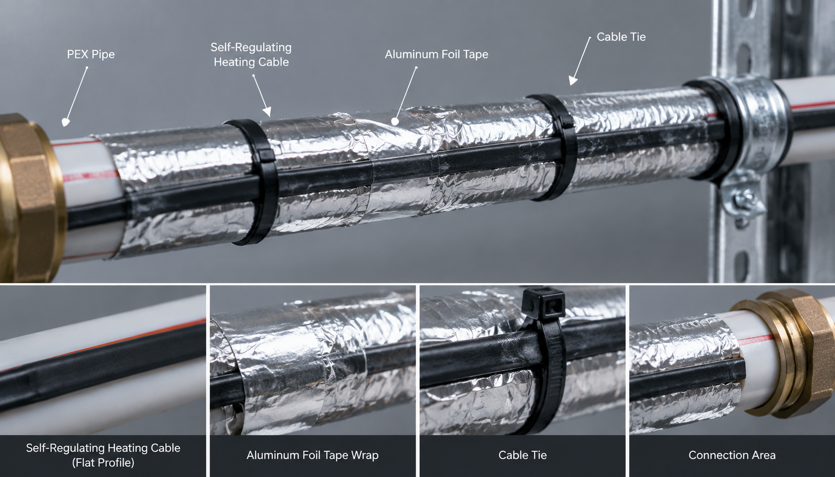
Technicians learning how to install heat tape on water pipes constructed from plastic must utilize continuous aluminum tape wrapping. Polyvinyl chloride and cross-linked polyethylene pipes conduct heat poorly, which creates localized hot spots beneath bare heating elements. Covering the heating cable with continuous aluminum tape spreads thermal energy evenly around the entire circumference of plastic piping. On standard steel piping, technicians apply fiberglass tape bands around the pipe circumference every three hundred millimeters along runs. Workers should apply extra tape wraps immediately adjacent to directional elbows, inline flanges, and electrical power termination boxes.
How Do You Apply Thermal Insulation Wrapping and Cladding?
Thermal insulation and protective metallic cladding form an essential barrier that preserves heat energy generated by the electric cable. The entire heat tracing system will fail to maintain target temperatures if wet or damaged insulation materials are installed. Mechanical contractors must install pre-formed insulation sections immediately after heating cable attachment passes the second electrical megger test. Rigid insulation sections must fit snugly around the traced pipe without pinching, cutting, or crushing the electric heating cable.
Per ASHRAE freeze protection guidelines, industrial plants select closed-cell cellular glass, rigid mineral wool, or elastomeric foam insulation. The selected insulation inner diameter must accommodate both the bare pipe diameter and the physical profile of the heating trace. Contractors must notch the inner wall of rigid calcium silicate insulation when passing over splice kits and temperature sensors. Forcing oversized insulation blocks over unnotched cable connections causes severe mechanical pinching that destroys internal heating conductors over time.
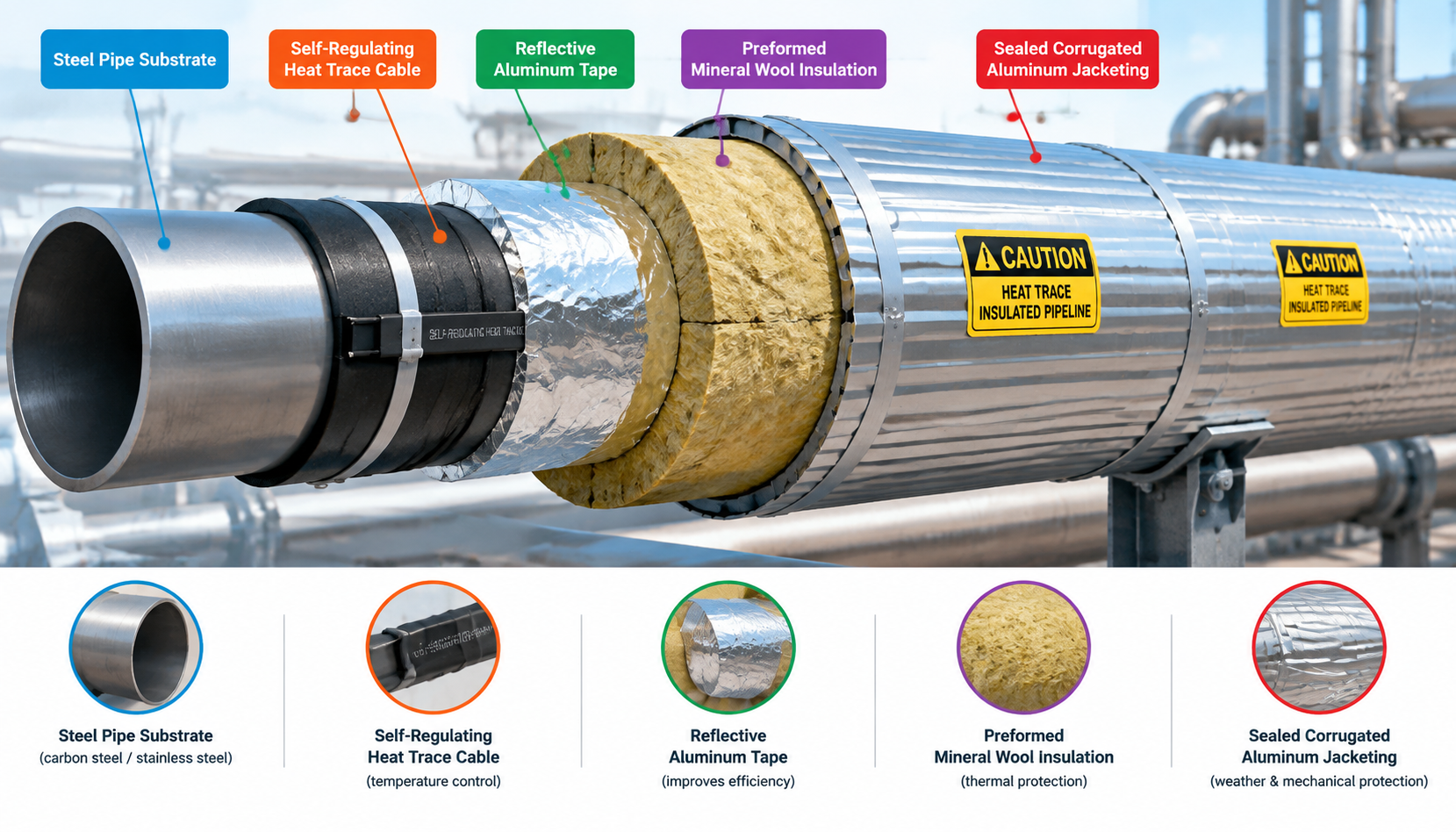
Installers must seal every longitudinal and circumferential joint on sheet metal cladding using industrial-grade silicone weatherproofing sealant. Moisture intrusion degrades insulation thermal performance significantly, which increases operational power consumption and causes severe corrosion under insulation. Technicians must exercise extreme caution when driving sheet metal screws into protective cladding to prevent puncturing the heating cable. Clear yellow warning labels must be placed along the external cladding surface at maximum three-meter intervals for safety. These conspicuous warning labels alert maintenance contractors to the presence of high-voltage electric heating cables beneath the metallic jacketing.
What Are the Final Commissioning and Quality Assurance Steps?
Final commissioning validates the overall mechanical integrity and electrical performance of the newly installed industrial pipe tracing system. Technicians must execute a third insulation resistance test after the mechanical insulation and metal cladding are fully installed. This critical post-insulation test confirms that sheet metal screws and jagged cladding edges did not damage the heating core. Resistance values must remain consistent with the initial baseline measurements recorded prior to the physical pipe installation process.
Technicians must mount the ambient sensing thermostat or resistance temperature detector bulb on the opposite side of the pipe. Placing the temperature sensor directly above the heating cable causes premature thermostat cycling and leaves distant fluid lines vulnerable. Commissioning engineers verify ground-fault circuit breaker tripping thresholds to ensure compliance with international industrial electrical safety guidelines. During initial system energization, technicians measure active inrush current spikes to verify that upstream electrical branch circuits handle loads. Handheld infrared thermal imaging cameras help technicians verify uniform heat distribution along the traced piping network without removing cladding.
How Should Engineers Select the Right Heating Cable for Industrial Piping?
Selecting the optimal heating cable technology is essential for ensuring long-term operational reliability across demanding industrial processing facilities. Plant engineers must evaluate operational maintain temperatures, maximum pipe exposure temperatures, and potential ambient chemical exposures before purchase. Self-regulating heating cables utilize a conductive carbon-polymer core that automatically adjusts thermal power output as ambient temperatures fluctuate. These intelligent heating cables can be overlapped safely in the field without generating dangerous localized thermal burnout hot spots.
Constant wattage heating cables deliver a fixed power output per meter regardless of fluctuating exterior pipe surface temperatures. Engineers prefer constant wattage cables for long transfer lines where high maintain temperatures exceed standard self-regulating cable thresholds. Facility managers must choose between durable polyolefin outer jackets for light duties and fluoropolymer jackets for harsh chemical environments. Fluoropolymer outer jackets provide superior protection against corrosive industrial solvents, aggressive hydrocarbons, and persistent chemical splash hazards. Youfu Thermal manufactures certified industrial self-regulating and constant wattage heating systems compliant with international IEC and UL benchmarks.
Frequently Asked Questions About Pipe Heat Trace Installation
Can you cross self-regulating heat trace cable over itself during pipe installation?
Yes, self-regulating heat trace cable can safely cross over itself on pipes because its conductive polymer core automatically reduces local heat output. The cable core automatically adjusts heat output at the crossover point to prevent thermal degradation and burnout. In contrast, constant wattage cables must never overlap because concentrated thermal build-up will burn through the primary electrical insulation. Always check the cable manufacturer datasheet before designing overlapping cable arrangements on valves or complex pipe fittings.
How do you safely install heat tape on plastic water pipes like PVC and PEX?
You must wrap plastic water pipes with continuous aluminum foil tape before and after applying the heating cable to distribute heat safely. Because plastic materials conduct heat poorly, bare electric heating cables create localized hot spots that can soften plastic piping. Applying an initial layer of aluminum foil tape spreads conductive thermal energy evenly around the entire pipe circumference. Technicians should always select self-regulating heating cables with low power densities when working with thermoplastic piping materials.
What is the minimum acceptable insulation resistance for electric heat tracing circuits?
The minimum acceptable insulation resistance is twenty megohms when tested with a direct current megohmmeter set to one thousand volts. Standard international specifications like IEEE 515 and IEC 60079-30-1 recommend testing cables at 500, 1000, or 2500 volts DC. Premium industrial installations typically aim for resistance values exceeding one hundred megohms on brand new heating cable circuits. Any circuit displaying a megger reading below twenty megohms indicates jacket compromise, water intrusion, or internal conductor damage.
Why should heat trace cable be installed at the four or eight o’clock positions?
Positioning the heating cable at four or eight o’clock protects the element from mechanical impact and avoids bottom pipe sediment. Placing the cable directly at six o’clock risks crushing the cable during pipe positioning or when support brackets shift. Furthermore, internal fluid sediment naturally accumulates along the bottom channel of pipes, which acts as an unwanted thermal insulator. Mounting the cable at four or eight o’clock facilitates natural convective thermal currents inside the fluid pipe.
Need Engineered Heat Tracing Solutions for Your Facility?
Youfu Thermal delivers high-performance electric heat tracing cables, connection accessories, and temperature control panels for worldwide industrial and commercial facilities. Our technical engineering specialists provide custom thermal calculations, isometric layout designs, and complete product packages tailored to your project requirements. Contact Youfu Thermal today to speak directly with an application engineer about your process maintenance or freeze protection system.